Von Duprin 6200 Series Electric Strike

$50.00

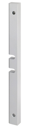
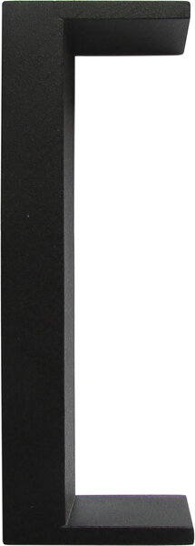
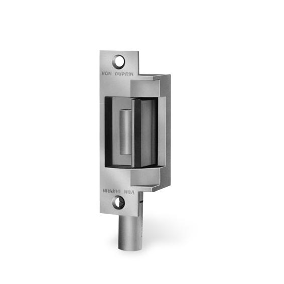
The 6200 Series includes 17 models of heavy-duty electric strikes. Integrated faceplate, stainless steel construction, and proven reliability make them ideal for new construction.

SKU: VON-6200-SERIES
Category:
Brands:

Description

The 6200 Series includes 17 models of heavy-duty electric strikes. Integrated faceplate, stainless steel construction, and proven reliability make them ideal for new construction.

Brand: Von Duprin

Manufacturer Part Number: VON-6200-SERIES

Source: Official product page

Additional information

fail_mode

fail safe, fail secure

voltage

12VDC, 24VDC

finish

605, 606, 612, 613, 629, 630, US10, US10B, US3, US32, US32D, US4

Reviews

There are no reviews yet.

Be the first to review “Von Duprin 6200 Series Electric Strike”

Your email address will not be published. Required fields are marked *

The 6200 Series comprises 17 models of heavy-duty electric strikes with stainless steel construction and integrated faceplates, designed for mortise and cylindrical locksets on single and pair doors, with fire-rated performance for new construction and retrofits.

Product specifications
Voltage 24 VDC standard (optional 12, 16, 28 VDC)
Current 24 VDC: 0.33 Amp continuous duty; 12 VDC: 0.6 Amp continuous duty
Strike ANSI grade ANSI/BHMA A156.31 Grade 1 (select models)
Fail safe secure Factory configurable fail safe or fail secure
Strength Static strength 1500 lbs; Dynamic strength 70 ft-lbs
Other Latch throw 3/4"; finishes BHMA 605, 606, 612, 613, 629, 630; compatible with Schlage, Von Duprin, and Falcon locksets; UL 294 listed; UL 1034 listed; fire rated UL 10C to 3 hours on single doors, 90 minutes on pair doors; CSFM listed
Low-voltage wiring Connection count needs review
PreparationChoose the exact 6200 strike model and backbox for the lockset, latchbolt position, door and frame. Use its own dimension and clearance drawing for preparation. Strike-pocket inserts and latchbolt compatibility depend on the selected model; some retrofit applications require extra frame preparation. Confirm the ordered solenoid, failure mode, monitoring and connector options before cutting or fitting. Obtain manufacturer application guidance for a lockset or retrofit not covered by the compatibility chart.
Electrical6200 Series supply options: 12V DC, 16V DC, 24V DC, 28V DC, continuous duty. Match the supply to the strike's ordered voltage; the all-model table does not identify the voltage of this catalogue item.
Preparation requiredYes
Conditional connectionsDC power to strike solenoid: cable runs quantity unspecified; conductor count unspecified; wire type not documented; size unspecified; shielding unspecified; rating unspecified; endpoints DC supply (J1) to Strike solenoid (P1); when Installation configuration is Base strike on DC power (24 VDC standard; 12/16/28 VDC optional); the diagram shows a DC supply linked to the solenoid through the plug connectors. The cable run boundary and conductor count are not documented.; AC supply via rectifier kit to solenoid: cable runs quantity unspecified; conductor count unspecified; wire type not documented; size unspecified; shielding unspecified; rating unspecified; endpoints AC supply (J1) to SO12/SO24 rectifier kit to Strike solenoid (P1); when Installation configuration is Optional accessory selected: IF the optional SO12/SO24 rectifier kit is selected for AC operation; the kit is plugged in-line to the solenoid.; Entry buzzer in parallel with solenoid circuit: cable runs quantity unspecified; conductor count unspecified; wire type not documented; size unspecified; shielding unspecified; rating unspecified; endpoints Entry buzzer to Strike solenoid circuit (P1); when Installation configuration is Optional accessory selected: IF the EB entry buzzer option is selected (fail-secure FSE only).; Dual monitor switch (DS/DS-LC) signal circuits: cable runs quantity unspecified; conductor count unspecified; wire type not documented; size unspecified; shielding unspecified; rating unspecified; endpoints Monitor switches S1 and S2 (P2/J2) to External monitoring input; when Installation configuration is Optional accessory selected: IF the DS or DS-LC dual monitor switch option is selected. The diagram shows S1 and S2 with color-coded leads, and the wiring configuration varies by backbox type and FS/FSE. Field cable count is not documented.

Official manufacturer documents