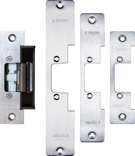
Von Duprin 6215 – Mortise strike, 9″ faceplate; own Folger Adam FA310-2

$50.00

Mortise strike, 9″ faceplate; own Folger Adam FA310-2 Variant record generated from manufacturer nomenclature (https://us.allegion.com/content/dam/allegion-us-2/web-files/von-duprin-/information-documents/Von_Duprin_6200_Series_Data_Sheet_105368.pdf); price inherited from product #4818 pending owner confirmation.

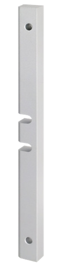
SKU: 6215
Category:
Brands:

Description

Mortise strike, 9″ faceplate; own Folger Adam FA310-2 Variant record generated from manufacturer nomenclature (https://us.allegion.com/content/dam/allegion-us-2/web-files/von-duprin-/information-documents/Von_Duprin_6200_Series_Data_Sheet_105368.pdf); price inherited from product #4818 pending owner confirmation.

Reviews

There are no reviews yet.

Be the first to review “Von Duprin 6215 – Mortise strike, 9″ faceplate; own Folger Adam FA310-2”

Your email address will not be published. Required fields are marked *

Product specifications
Low-voltage wiring Connection count needs review
PreparationThe 6215 is a mortise or cylindrical-lockset electric strike with a 9" face plate and a 1-5/8" backbox depth. It replaces the Folger Adam FA 310-2. The door frame needs a prepared cutout that can take the strike body. The lockset must be a compatible mortise or cylindrical type. Frame-prep details beyond the documented depth and face plate length are not given in the supplied text.
Electrical6200 Series supply options: 12V DC, 16V DC, 24V DC, 28V DC, continuous duty. Match the supply to the strike's ordered voltage; the all-model table does not identify the voltage of this catalogue item.
Preparation requiredYes
Conditional connectionsAC supply through the optional rectifier kit to the solenoid: cable runs quantity unspecified; conductor count unspecified; wire type not documented; size unspecified; shielding unspecified; rating unspecified; endpoints AC supply to J1 to Rectifier kit (So Kit) to P1A/J1A to P1 to Solenoid; when Installation configuration is Optional accessory selected: IF AC power is used, the optional rectifier kit (S012 or S024) is selected. The kit converts 12 VAC or 24 VAC to DC for the solenoid.; Entry buzzer circuit: cable runs quantity unspecified; conductor count unspecified; wire type not documented; size unspecified; shielding unspecified; rating unspecified; endpoints DC supply to J1/P1 to Buzzer to Solenoid; when Installation configuration is Optional accessory selected: IF the EB entry buzzer option is selected. It is available in fail-secure (FSE) only. The diagram shows the buzzer in line with the solenoid.; AC supply through the optional rectifier kit to the solenoid: cable runs quantity unspecified; conductor count unspecified; wire type not documented; size unspecified; shielding unspecified; rating unspecified; endpoints AC supply (J1) to Rectifier kit (P1A/J1A) to Solenoid (P1); when Installation configuration is Optional accessory selected: IF the optional rectifier kit (S012 or S024) is selected for AC operation. The diagram shows an AC supply at J1, the rectifier kit, and the solenoid at P1.; Entry buzzer in series with the solenoid circuit: cable runs quantity unspecified; conductor count unspecified; wire type not documented; size unspecified; shielding unspecified; rating unspecified; endpoints DC supply (J1) to Buzzer and solenoid (P1); when Installation configuration is Optional accessory selected: IF the optional EB entry buzzer is selected (fail-secure only). The 'DC with Buzzer' diagram shows the buzzer connected at P1 together with the solenoid.; Scoped installation connections for 6215: cable runs quantity unspecified; conductor count unspecified; wire type not documented; size unspecified; shielding unspecified; rating Only the separately documented plain DC interface has a verified conductor count. Other option circuits and cable-run quantities remain unknown.; endpoints 6215 selected power connector and supported optional circuits to Selected external supply and control/monitor equipment; when Installation configuration is Base power: Connect the external supply to the strike solenoid via the documented power connector path; match the ordered solenoid voltage. Dc: Use direct DC wiring for the matching DC solenoid. Ac: Only with the matching rectifier: S012 converts 12 VAC to 12 VDC; S024 converts 24 VAC to 24 VDC. Mode: FSE requires power to unlock and remains locked on power loss; FS requires power to lock and unlocks on power loss. Preserve the actual ordered configuration. Optional eb: Entry buzzer only when ordered, and only in FSE configuration. Optional ds: Only if DS/DS-LC is ordered and offered for this exact model: separate latch-bolt/strike-lip monitoring circuits. Contact state and configuration depend on backbox and FS/FSE; use the exact variant wiring diagram.; Plain DC supply connection at the external power interface: cable runs quantity unspecified; 2 conductor(s); wire type not documented; size unspecified; shielding unspecified; rating Match the ordered DC coil and connector; additional optional circuits require their own supported configuration.; endpoints External 12 VDC or 24 VDC supply interface/J1 to Strike power connector P1; when Installation configuration is Only the plain DC circuit with the selected matching 12 VDC or 24 VDC solenoid/connector. Two conductors at this external supply interface. No buzzer, DS/DS-LC monitoring or AC rectifier branch is included. This is not a total installation count or a cable-run/new-pull quantity.