
Description
Receiver, Wireless, 1 Channel, w/
Sequencing Feature
Used in conjunction w/ Wireless
Actuators & Transmitter(s)
G115
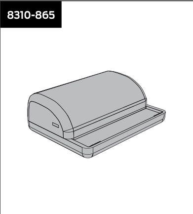
Model 8310-865. Installer-grade transmitter.
Receiver, Wireless, 1 Channel, w/
Sequencing Feature
Used in conjunction w/ Wireless
Actuators & Transmitter(s)
G115
| Brand | LCN |
|---|
LCN 8310 Series is a modular system of touchless and push-plate door actuators, wireless transmitter/receiver sets, mounting boxes, escutcheons, weather/trim rings, safety sensors, and accessory kits used to remotely actuate LCN automatic swing-door operators (e.g., 4630/4640, 7900 pneumatic auto-equalizer, 9100 Benchmark, Senior Swing 2800/9500, Mid Swing 2900/9700 series). Touchless actuators and hardwired push plates require a wired, low-voltage power/control connection back to the door operator control box; most are also compatible with a 433 MHz or 900 MHz wireless transmitter/receiver pair for wireless actuation signaling instead of a run of activation wire. A subset of push plates (8310-852WP/853WP) are fully wireless/battery powered with no field control wiring at the plate itself (only the receiver, sold separately, is wired to the operator).
| Touchless actuator supply (8310-813) | 12-24 VAC ±10% or 12-24 VDC +30%/-10%, SELV-compatible power supplies only; power consumption < 1.5W; output is a voltage-free relay (max 60VDC/125VAC, 1A resistive, 30W) |
|---|---|
| 900 MHz receiver input voltage (8310-880) | 12-24 VAC/VDC; relay contact rating 1.0A@30VDC, 0.3A@60VDC, 0.5A@125VAC |
| Wireless transmitter power consumption (900 MHz) | 30mA (standard TX) / 40mA (RX) / 22mA (retrofit TX) |
| Receiver capacity | up to 74-75 transmitters per standard receiver; unlimited for 'universal' mode |
| Low-voltage wiring | Required |
| Basis | Structured, independently qualified product connection evidence |
| Preparation | Shut off power to the work area before wiring. Place the receiver and wiring so moving parts cannot catch or damage them. Confirm the actual operator and activation configuration before connection. |
| Electrical | The receiver input is 12-24 VAC/VDC. Receiver terminals 1 and 2 are the control/transformer power connection; terminal 3 is control common, 4 is normally open activation and 5 is normally closed. The receiver relay must not directly interrupt power to a magnetic lock or electric strike; use a logic module or isolation relay for those loads. |
| Electrical wiring required | Yes |
| Conditional connections | Receiver power pair: cable runs quantity unspecified; 2 conductor(s); wire type Copper conductors; Class2 low-voltage interface. Gauge and shielding not stated.; size unspecified; shielding unspecified; rating Copper conductors; matched4630/4640 Class2 low-voltage interface. Gauge, shielding and physical cable-jacket quantity are not specified by these cited instructions.; endpoints 4630/4640 operator controller power to 8310-865 receiver power terminals 1 and 2; when Installation configuration is Only for the 4630/4640 Electric Auto-Equalizer interface drawn at the upper left of manufacturer page 4: two conductors for this connection at receiver terminals 1 and 2. The power and activation pairs are distinct. Protective earth is not included. The drawing does not establish cable-run/jacket quantities or new cable pulls. Other operator models require their own diagram.; Receiver activation pair: cable runs quantity unspecified; 2 conductor(s); wire type Copper conductors; Class2 low-voltage interface. Gauge and shielding not stated.; size unspecified; shielding unspecified; rating Copper conductors; matched4630/4640 Class2 low-voltage interface. Gauge, shielding and physical cable-jacket quantity are not specified by these cited instructions.; endpoints 4630/4640 operator controller activation and common to 8310-865 receiver relay terminals 3 and 4; when Installation configuration is Only for the 4630/4640 Electric Auto-Equalizer interface drawn at the upper left of manufacturer page 4: two conductors for this connection at receiver terminals 3 and 4. The power and activation pairs are distinct. Protective earth is not included. The drawing does not establish cable-run/jacket quantities or new cable pulls. Other operator models require their own diagram. |
Reviews
There are no reviews yet.