
Description
Series: CX-33
Type: Advanced Logic Relay
Advanced Logic Relay
Brand: Camden
Manufacturer Part Number: CX-33
Source: Camden Controls product page
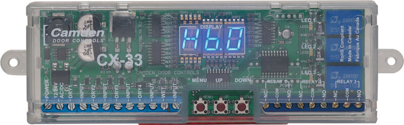
Advanced Logic Relay
Series: CX-33
Type: Advanced Logic Relay
Advanced Logic Relay
Brand: Camden
Manufacturer Part Number: CX-33
Source: Camden Controls product page
Camden's CX-33 is an advanced logic relay for door control, available in a prewired power supply cabinet (CX-33PS) with selectable 12V or 24V DC power, color-coded wiring terminals, and a metal enclosure. It offers 15 selectable operating modes via three programming buttons, short-circuit and thermal overload protection, and a 2 Amp UL-listed power supply that can power controls, annunciators, and electrified locking devices.
| Operating voltage | 12/24 Volts, AC/DC |
|---|---|
| Current draw | 105 mA standby, 320 mA max. |
| Inputs | 4 x 'dry' contacts and 1 x 'wet' contact (4.5-120V AC/DC, optically isolated, non-polarity sensitive) |
| Response time | 0.5 seconds |
| Relay output | 3 x Form C (SPDT) |
| Contact rating | 3 amps @ 24 VDC |
| Temperature range | -22°F to 185°F (-30°C to 85°C) |
| Low-voltage wiring | Required |
| Basis | Structured, independently qualified product connection evidence |
| Preparation | Mount the module in a clean, dry location protected from the elements, such as a metal enclosure, operator header or above a false ceiling. Keep the programming buttons and terminal strips accessible while wiring and adjusting it, then secure with the supplied Velcro or sheet-metal screws. Confirm the supplied fastener size: the package list and mounting specification differ. With power off, select the required operating mode and follow that mode diagram for input functions, relay functions and timing; read the instructions and make the required adjustments before applying power. |
| Electrical | Connect 12/24VAC/DC operating power to P1 terminals1 and2, non-polarized, using two circuit conductors; current draw is 105mA standby and 320mA maximum. Four separate dry-input pairs each use two conductors when selected. P1 terminals11/12 accept a powered signal; the conditional conductor count here applies only to a compatible low-voltage signal. The manual gives a 4.5V activation threshold while the terminal drawing labels the input range starting at 5V; verify the actual revision and signal. Each selected P2 dry relay output uses COM with NO or NC (two conductors), or COM with both throws (three). Outputs supply no power. Select the mode and connected equipment before assigning functions; do not add alternative throws together. A regulated supply is recommended for long-duration washroom strike operation. Physical cable runs, type, gauge and shielding remain dependent on equipment and layout. |
| Preparation required | Yes |
| Electrical wiring required | Yes |
| Conditional connections | Activating and input devices wired to the dry and wet inputs: cable runs quantity unspecified; conductor count unspecified; wire type not documented; size unspecified; shielding unspecified; rating unspecified; endpoints Switches, sensors or panels to DRY 1-4 and WET inputs; when Installation configuration is Depends on the selected operating mode and the devices used. For example, in Mode 1 momentary devices go to DRY 1 or WET 1.; Apartment/Condo (Mode 5) inputs: interphone panel dry contact to DRY 1 or powered signal to WET input, courtesy switch to DRY 2, inside switch to DRY 3: cable runs quantity unspecified; conductor count unspecified; wire type not documented; size unspecified; shielding unspecified; rating unspecified; endpoints Interphone panel to Vestibule (courtesy) switch to Inside switch to CX-33 DRY 1, WET, DRY 2, DRY 3 inputs; when Installation configuration is Only if Mode 5 Apartment/Condo is selected. An optional key switch goes to DRY 1 or DRY 3, and an optional fire panel input goes to DRY 4. The optional 50 ohm 1 W resistor is used in series with the Wet input if stray voltage is present.; Mode 5 outputs: Relay 1 to the electric lock or strike and Relay 2 to the door operator (dry contacts): cable runs quantity unspecified; conductor count unspecified; wire type not documented; size unspecified; shielding unspecified; rating unspecified; endpoints CX-33 Relay 1 terminals to Electric strike or lock to CX-33 Relay 2 terminals to Door operator; when Installation configuration is Only if Mode 5 is selected. Relay outputs are dry contacts, so the strike needs a separate 12-24 V power source.; Mag lock (Mode 11) connections: wall switches to DRY 1/WET, fire alarm to DRY 3, door position switch to DRY 4, mag lock to Relay 1 COM and N.C., door operator to Relay 2 COM and N.O.: cable runs quantity unspecified; conductor count unspecified; wire type not documented; size unspecified; shielding unspecified; rating unspecified; endpoints Wall switches to N.O. fire alarm to Door position switch to Mag lock to Door operator to CX-33 inputs and Relays 1 and 2; when Installation configuration is Only if Mode 11 (mag lock with N.O. fire alarm) is selected. Relay 3 output is optional.; Mag lock and door operator relay outputs, with N.O. fire alarm input and door position switch inputs: cable runs quantity unspecified; conductor count unspecified; wire type not documented; size unspecified; shielding unspecified; rating unspecified; endpoints Mag lock to Relay 1 Common and N.C. to Door operator to Relay 2 Common and N.O. to Wall switches to DRY 1 and/or WET to N.O. fire alarm to DRY 3 to Door position switch to DRY 4; when Installation configuration is IF Mode 11 (mag lock with N.O. fire alarm) is the selected configuration. A maintained device on DRY 2 is optional and the Relay 3 output is optional. The relay outputs are dry contacts, not powered. Cable counts are not stated in the text.; Delayed relay activation: siren, lock and status outputs with fire alarm, bypass key switch and door position inputs: cable runs quantity unspecified; conductor count unspecified; wire type not documented; size unspecified; shielding unspecified; rating unspecified; endpoints Switch to Input 1 to Fire alarm to DRY 2 or WET 1 to Bypass/shunt key switch to DRY 3 to N/C door position switch to DRY 4 to Relay 1 to local siren to Relay 2 to electric lock to Relay 3 to status monitoring; when Installation configuration is IF Mode 14 (delayed relay activation) is the selected configuration. Not for use as UL compliant delayed egress.; Wet input series resistor for older telephone entry panels: cable runs quantity unspecified; conductor count unspecified; wire type not documented; size unspecified; shielding unspecified; rating unspecified; endpoints 50 ohm 1 W supplied resistor to Wet input in series; when Installation configuration is IF an older telephone entry panel outputs a stray voltage above 3 V when inactive and wet-input wiring is used. This is a series component, not a documented new cable run.; CX-33 operating power P1: cable runs quantity unspecified; 2 conductor(s); wire type not documented; size unspecified; shielding unspecified; rating Field cable type, gauge, shielding and physical cable-run quantities unspecified.; endpoints Compatible12/24VAC/DC supply to P1 terminals1 and2; when Installation configuration is Non-polarized operating power input; dry outputs supply no power.; CX-33 selected dry input 1: cable runs quantity unspecified; 2 conductor(s); wire type not documented; size unspecified; shielding unspecified; rating Field cable type, gauge, shielding and physical cable-run quantities unspecified.; endpoints Selected external dry contact to P1 terminals3 and4; when Installation configuration is Only when input1 is used by the selected operating mode; function follows that mode diagram.; CX-33 selected dry input 2: cable runs quantity unspecified; 2 conductor(s); wire type not documented; size unspecified; shielding unspecified; rating Field cable type, gauge, shielding and physical cable-run quantities unspecified.; endpoints Selected external dry contact to P1 terminals5 and6; when Installation configuration is Only when input2 is used by the selected operating mode; function follows that mode diagram.; CX-33 selected dry input 3: cable runs quantity unspecified; 2 conductor(s); wire type not documented; size unspecified; shielding unspecified; rating Field cable type, gauge, shielding and physical cable-run quantities unspecified.; endpoints Selected external dry contact to P1 terminals7 and8; when Installation configuration is Only when input3 is used by the selected operating mode; function follows that mode diagram.; CX-33 selected dry input 4: cable runs quantity unspecified; 2 conductor(s); wire type not documented; size unspecified; shielding unspecified; rating Field cable type, gauge, shielding and physical cable-run quantities unspecified.; endpoints Selected external dry contact to P1 terminals9 and10; when Installation configuration is Only when input4 is used by the selected operating mode; function follows that mode diagram.; CX-33 selected low-voltage powered input: cable runs quantity unspecified; 2 conductor(s); wire type not documented; size unspecified; shielding unspecified; rating Field cable type, gauge, shielding and physical cable-run quantities unspecified.; endpoints Compatible low-voltage signal source to P1 terminals11 +Wet and12 -Input; when Installation configuration is Only for a compatible low-voltage signal; verify threshold against the actual revision. Excludes higher-voltage configurations.; CX-33 relay1 COM with NO: cable runs quantity unspecified; 2 conductor(s); wire type not documented; size unspecified; shielding unspecified; rating Field cable type, gauge, shielding and physical cable-run quantities unspecified.; endpoints Selected low-voltage controlled circuit to P2 terminals2, 3; when Installation configuration is When relay1 uses NO in the selected mode; throw alternatives are not additive.; CX-33 relay1 COM with NC: cable runs quantity unspecified; 2 conductor(s); wire type not documented; size unspecified; shielding unspecified; rating Field cable type, gauge, shielding and physical cable-run quantities unspecified.; endpoints Selected low-voltage controlled circuit to P2 terminals2, 1; when Installation configuration is When relay1 uses NC in the selected mode; throw alternatives are not additive.; CX-33 relay1 COM with NO and NC: cable runs quantity unspecified; 3 conductor(s); wire type not documented; size unspecified; shielding unspecified; rating Field cable type, gauge, shielding and physical cable-run quantities unspecified.; endpoints Selected low-voltage controlled circuit to P2 terminals2, 3, 1; when Installation configuration is When relay1 uses NO and NC in the selected mode; throw alternatives are not additive.; CX-33 relay2 COM with NO: cable runs quantity unspecified; 2 conductor(s); wire type not documented; size unspecified; shielding unspecified; rating Field cable type, gauge, shielding and physical cable-run quantities unspecified.; endpoints Selected low-voltage controlled circuit to P2 terminals5, 6; when Installation configuration is When relay2 uses NO in the selected mode; throw alternatives are not additive.; CX-33 relay2 COM with NC: cable runs quantity unspecified; 2 conductor(s); wire type not documented; size unspecified; shielding unspecified; rating Field cable type, gauge, shielding and physical cable-run quantities unspecified.; endpoints Selected low-voltage controlled circuit to P2 terminals5, 4; when Installation configuration is When relay2 uses NC in the selected mode; throw alternatives are not additive.; CX-33 relay2 COM with NO and NC: cable runs quantity unspecified; 3 conductor(s); wire type not documented; size unspecified; shielding unspecified; rating Field cable type, gauge, shielding and physical cable-run quantities unspecified.; endpoints Selected low-voltage controlled circuit to P2 terminals5, 6, 4; when Installation configuration is When relay2 uses NO and NC in the selected mode; throw alternatives are not additive.; CX-33 relay3 COM with NO: cable runs quantity unspecified; 2 conductor(s); wire type not documented; size unspecified; shielding unspecified; rating Field cable type, gauge, shielding and physical cable-run quantities unspecified.; endpoints Selected low-voltage controlled circuit to P2 terminals8, 9; when Installation configuration is When relay3 uses NO in the selected mode; throw alternatives are not additive.; CX-33 relay3 COM with NC: cable runs quantity unspecified; 2 conductor(s); wire type not documented; size unspecified; shielding unspecified; rating Field cable type, gauge, shielding and physical cable-run quantities unspecified.; endpoints Selected low-voltage controlled circuit to P2 terminals8, 7; when Installation configuration is When relay3 uses NC in the selected mode; throw alternatives are not additive.; CX-33 relay3 COM with NO and NC: cable runs quantity unspecified; 3 conductor(s); wire type not documented; size unspecified; shielding unspecified; rating Field cable type, gauge, shielding and physical cable-run quantities unspecified.; endpoints Selected low-voltage controlled circuit to P2 terminals8, 9, 7; when Installation configuration is When relay3 uses NO and NC in the selected mode; throw alternatives are not additive. |
Reviews
There are no reviews yet.