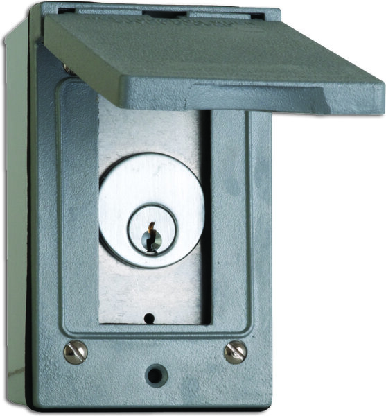
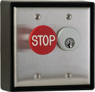
Schlage 653-0505 – (2) SPDT momentary, bi-direction

$75.00

(2) SPDT momentary, bi-direction Variant record generated from manufacturer nomenclature (https://us.allegion.com/content/dam/allegion-us-2/web-files/schlage/information-documents/Schlage_Key_Switch_Data_Sheet_103907.pdf); price inherited from product #4763 pending owner confirmation.
SKU: 653-0505
Category:
Brands:

Description

(2) SPDT momentary, bi-direction Variant record generated from manufacturer nomenclature (https://us.allegion.com/content/dam/allegion-us-2/web-files/schlage/information-documents/Schlage_Key_Switch_Data_Sheet_103907.pdf); price inherited from product #4763 pending owner confirmation.

Reviews

There are no reviews yet.

Be the first to review “Schlage 653-0505 – (2) SPDT momentary, bi-direction”

Your email address will not be published. Required fields are marked *

Product specifications
Low-voltage wiring Connection count needs review
PreparationPrepare the mounting area using the full-scale manufacturer 653 template and install in a standard single-gang box. Fit the selected compatible mortise cylinder and required blocking/spacer ring. The manufacturer recommended cutout has a minimum depth of 1-3/4 inch.
ElectricalKey-operated passive switch contacts are rated 5 A at 30 VDC; this is a switched-load rating, not a device power-input requirement. Optional L2 indicator LEDs use a separate 12/24 VDC supply.
Preparation requiredYes
Electrical wiring requiredYes
Conditional connectionsScoped installation connections for 653-0505: cable runs quantity unspecified; conductor count unspecified; wire type not documented; size unspecified; shielding unspecified; rating Select the actual circuit and options. Field-conductor and cable-run counts are not established by contact/pole totals.; endpoints 653-0505 selected switch contacts to Selected external controlled circuit; separate optional LED supply and ATS monitor where fitted; when Installation configuration is Switch function: two SPDT momentary, bidirectional Base circuit: Connect the selected key-operated switch contacts to the external controlled circuit according to the required NO/NC action and exact ordered function. Optional l2: Only when L2 is fitted, power the LEDs separately at 12/24 VDC; polarity is red positive, black negative in the installation diagram. Optional ats: Only when ATS is fitted, the anti-tamper contact closes with the cover on and requires its own selected monitoring circuit.