Schlage 1910 Series Electric Horns

$50.00

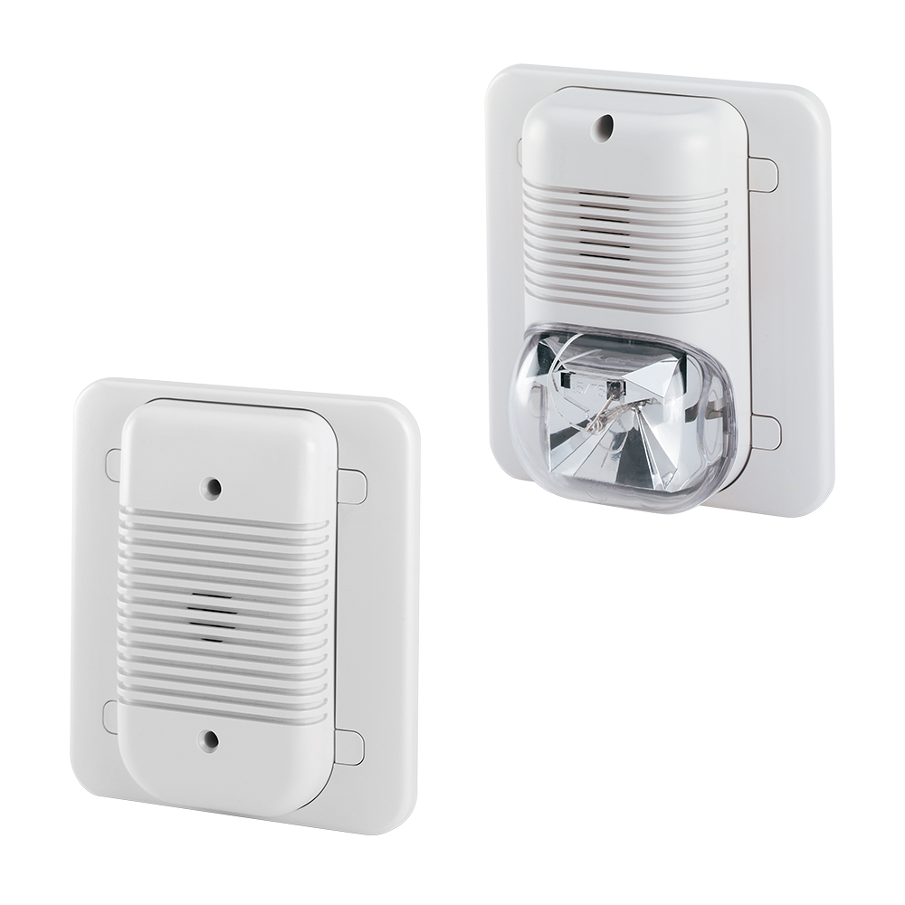
Integrate the Schlage 1910 electric horn into a security system as a local audible warning device that is easy to configure to your key system needs.

SKU: SCH-1910-SERIES-ELECTRIC-HORNS
Category:
Brands:

Description

Integrate the Schlage 1910 electric horn into a security system as a local audible warning device that is easy to configure to your key system needs.

Brand: Schlage

Manufacturer Part Number: SCH-1910-SERIES-ELECTRIC-HORNS

Source: Official product page

Additional information

voltage

12/24VDC

Reviews

There are no reviews yet.

Be the first to review “Schlage 1910 Series Electric Horns”

Your email address will not be published. Required fields are marked *

The Schlage 1910 Series electric horns are audible warning devices for building management systems that can signal open doors or general alarms, available in horn-only, strobe, and latching-capable models, in flush-mount or surface-mount configurations.

Product specifications
Models 1910-1, 1910S-1, L1910-1, L1910S-1
Voltage standard 12/24 VDC (1910-1); 24 VDC (others)
Power @ 12 VDC <14 mA
Power @ 24 VDC <28 mA (horn); <71 mA (with strobe)
Sound level anechoic 102 dBA @ 30V
Sound level reverberant 88 dBA @ 30V
Dimensions 4.75"W x 5.5"H
Operating temperature 32 to 120 F
Tone options 6 volume combinations, continuous or intermittent
Installation flush mount or surface mount
Certifications UL294, UL1034
Color off-white
Low-voltage wiring Connection count needs review
PreparationSelect the exact 1910 horn, horn-strobe or latching horn-strobe model and its mounting method before preparing the installation. For the documented 1910S-1/L1910S-1 horn-strobe assembly, secure the flush plate to its recessed back box or secure the surface back box to the mounting plate, complete field wiring, hook the assembly onto the plate and secure its captured screw. The supplied Torx screw is an optional tamper-resistant replacement. Set the strobe/audio options with power removed. Other 1910 variants require their matching instructions.
ElectricalFor the documented 1910S-1 and L1910S-1 assemblies, the installation manual specifies 12 or 24 VDC and 28 mA maximum average current. Keep these supply specifications distinct from the switch contacts that trigger or inhibit the alarm. The standard model stops when its monitored conditions restore; the latching model has separate reset/inhibit functions and can remain active after the door closes. Select the exact model, monitored lock/door contacts and reset/inhibit application before assigning conductors. The horn-strobe circuit must not be transferred to another 1910 family variant without its matching instructions.
Preparation requiredYes
Electrical wiring requiredYes
Conditional connectionsDC power supply to horn strobe (1910S-1 typical wiring): cable runs quantity unspecified; conductor count unspecified; wire type not documented; size unspecified; shielding unspecified; rating unspecified; endpoints Power supply (+) to Power supply (-) to 1910S-1 horn strobe terminals; when Installation configuration is 1910S-1 only: terminals on the front of the mounting plate. Power supply (-) is shown on one terminal and power supply (+) on the other two terminals. The supply is 24 VDC per the model list; the instructions give 12 or 24 VDC.; Door-open / latchbolt-retract activation via monitor strike and door position switch (1910S-1 typical wiring): cable runs quantity unspecified; conductor count unspecified; wire type not documented; size unspecified; shielding unspecified; rating unspecified; endpoints Power supply (+) to Monitor strike switch to Door position switch to 1910S-1 horn strobe (+) terminal; when Installation configuration is 1910S-1 only: this is the typical wiring for activating the horn on latchbolt retract or door open. The monitor strike and door position switches are shown as external devices, and whether they are required for a given job is a site choice.

Official manufacturer documents