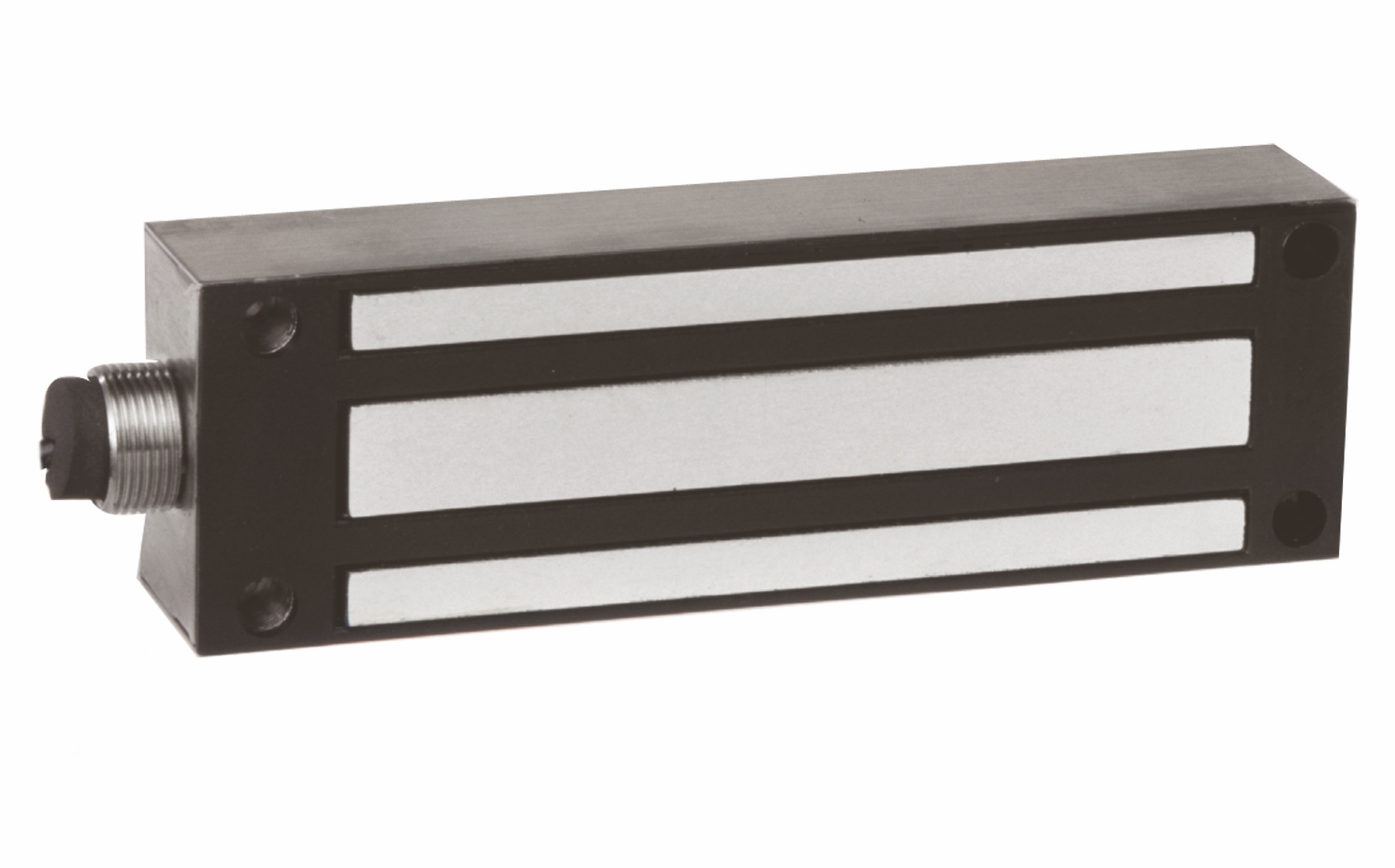
CX-94S – CX-94 Series: Gate Locks

CX-94 Series: Gate Locks – Camden Door Controls

Brands:

Description

CX-94 Series: Gate Locks – Camden Door Controls

Source: https://www.camdencontrols.com/category/locking/Magnetic_Locks/products/CX_94S

Resources:
https://www.camdencontrols.com/pipelines/resource/8127_Magnetic_Lock_Cross_Reference.pdf
https://www.camdencontrols.com/pipelines/resource/8128_59RFE5JLGQZ60WJTDNNP.pdf
https://www.camdencontrols.com/pipelines/resource/8129_CX_94S_12LS_Spec_Sheet.pdf
https://www.camdencontrols.com/pipelines/resource/8130_HAMYLOL0ZS14OCR7LHT4.pdf
https://www.camdencontrols.com/pipelines/resource/8131_CX_94S_12LS_Manual_R1.pdf
https://www.camdencontrols.com/pipelines/resource/8132_LZYHFX2URM8S2CX6VBHI.pdf

Reviews

There are no reviews yet.

Be the first to review “CX-94S – CX-94 Series: Gate Locks”

Your email address will not be published. Required fields are marked *

Camden CX-94S-12LS gate locks are rugged magnetic locks designed for outdoor applications. They offer exceptional performance and value with ultra low current draw, making them the ideal choice for most gating projects.

Product specifications
Low-voltage wiring Connection count needs review
PreparationSurface mounting needs layout and drilled holes. The magnet mounts to the gate/door frame, and the armature plate mounts to the gate/door with the supplied hardware. Components must be handled carefully to avoid damaging the magnet and armature surfaces.
ElectricalFor CX-94S-12LS follow the selected DC voltage diagram. The lower-voltage arrangement joins green/orange on negative and red/black on positive; the higher-voltage arrangement joins and isolates black/green, with orange negative and red positive. The brown common, yellow NO and blue NC lock-status circuit is separate from power. Factory wire joins do not establish field cable counts or physical runs.
Preparation requiredYes
Electrical wiring requiredYes
Conditional connectionsLock power input (12 VDC configuration): cable runs quantity unspecified; conductor count unspecified; wire type not documented; size unspecified; shielding unspecified; rating unspecified; endpoints Lock leads (green, orange, red, black) to 12 VDC power source; when Installation configuration is Base product, 12 VDC selection: green+orange tied to negative, red+black tied to positive. Factory leads are not field cable cores.; Lock power input (24 VDC configuration): cable runs quantity unspecified; conductor count unspecified; wire type not documented; size unspecified; shielding unspecified; rating unspecified; endpoints Lock leads (black, green, orange, red) to 24 VDC power source; when Installation configuration is Base product, 24 VDC selection: black+green tied together, orange to negative, red to positive. Factory leads are not field cable cores.; Lock status sensor (reed switch) output: cable runs quantity unspecified; conductor count unspecified; wire type not documented; size unspecified; shielding unspecified; rating unspecified; endpoints Brown COM / yellow NO / blue NC leads to Monitoring or status circuit; when Installation configuration is Base product; applies only IF the lock status output is used. The reed switch is rated 0.5 A @ 30 VDC in the manual (1 A @ 30 VDC elsewhere), a rating discrepancy. NO and NC are alternatives, and using all leads is not implied.

Official manufacturer documents