
Description
1200lb surface mount gate lock w/ lock sensor and relay Variant record generated from manufacturer nomenclature (https://www.camdencontrols.com/products/CX_94S); price inherited from product #3410 pending owner confirmation.
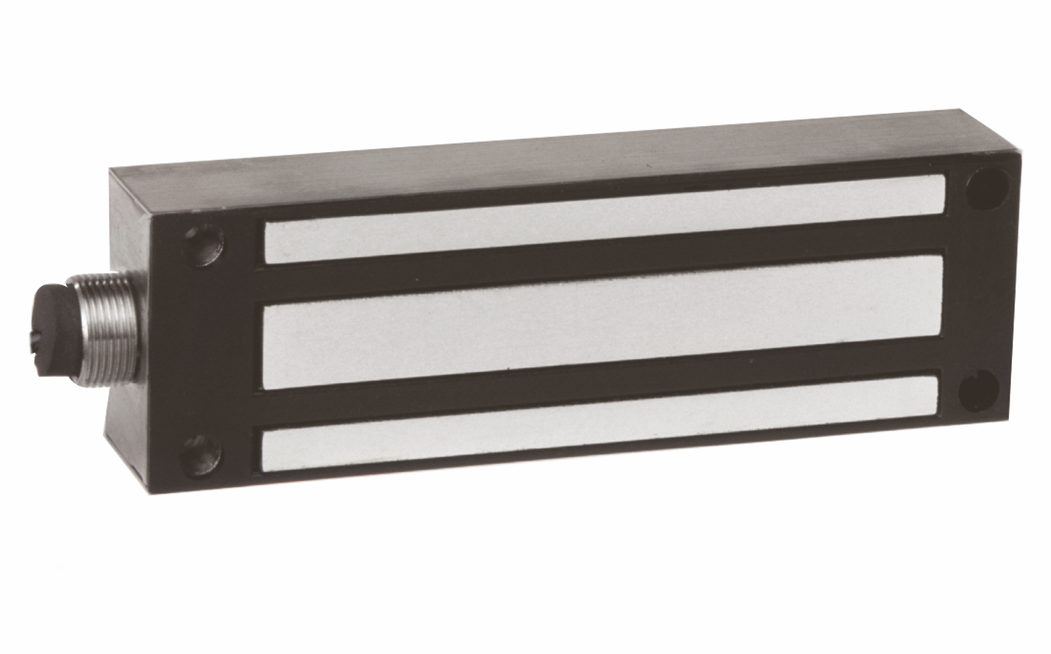
1200lb surface mount gate lock w/ lock sensor and relay Variant record generated from manufacturer nomenclature (https://www.camdencontrols.com/products/CX_94S); price inherited from product #3410 pending owner confirmation.
1200lb surface mount gate lock w/ lock sensor and relay Variant record generated from manufacturer nomenclature (https://www.camdencontrols.com/products/CX_94S); price inherited from product #3410 pending owner confirmation.
| Low-voltage wiring | Required |
|---|---|
| Basis | Structured, independently qualified product connection evidence |
| Preparation | Mount the magnet to the gate or door frame and the armature to the moving gate or door using the supplied hardware, allowing the armature to pivot about its center. Lay out fixing positions with the opening normally closed using the original model dimensions and site measurements. Install the screws finger-tight, verify alignment, then tighten as instructed. Protect the mating magnet and armature faces from damage and use the exact conduit entry and supporting structure for the outdoor installation. |
| Electrical | Operating voltage is12 or24 VDC, selected for the gate lock. In12 VDC configuration the manual joins green/orange to negative and red/black to positive; in24 VDC configuration it joins black/green locally, with orange to negative and red to positive. Follow the illustrated DC-side switching arrangement and isolate the wiring from earth as instructed. Keep status contacts separate: brown COM, yellow NO and blue NC. The manual gives a bond-sensor contact rating of1 A at30 VDC in its specification section and a reed-switch contact rating of0.5 A at30 VDC in its wiring section. Confirm the actual sensor/revision and approved switched load. Local joins and monitor leads do not determine cable jackets or run quantities. |
| Preparation required | Yes |
| Electrical wiring required | Yes |
| Conditional connections | Lock power input, 24 V DC configuration: cable runs quantity unspecified; conductor count unspecified; wire type not documented; size unspecified; shielding unspecified; rating unspecified; endpoints Lock leads (black, green, orange, red) to 24 V DC power source; when Installation configuration is IF the lock is wired for 24 V DC: tie black and green together with wire nuts or tape them off, connect the power source ground (-) to the orange wire, and connect the positive (+) lead to the red wire. The documented lock leads are factory leads; the field cable count is not documented.; Lock status sensor (reed switch) output: cable runs quantity unspecified; conductor count unspecified; wire type not documented; size unspecified; shielding unspecified; rating unspecified; endpoints Reed switch leads (brown COM, yellow NO, blue NC) to External status monitoring circuit; when Installation configuration is Only IF the lock status signal is used. The reed switch is rated 0.5 A @ 30 VDC (the datasheet lists a 1 A @ 30 VDC contact rating); do not exceed the rated capacity. Which leads are used depends on whether NO or NC is wanted, and the external endpoint is not documented.; CX-94S-12LS direct DC field power pair: cable runs quantity unspecified; 2 conductor(s); wire type not documented; size unspecified; shielding unspecified; rating Select cable gauge/type from load, distance and installation; field cable jacket/run quantities unspecified.; endpoints External DC supply/control circuit to Mounted gate-lock power input boundary; when Installation configuration is If configured for the illustrated direct12 or24VDC power circuit. Count covers only active field power conductors; local coil joins, optional status wiring and upstream control wiring are separate. |

Reviews
There are no reviews yet.