
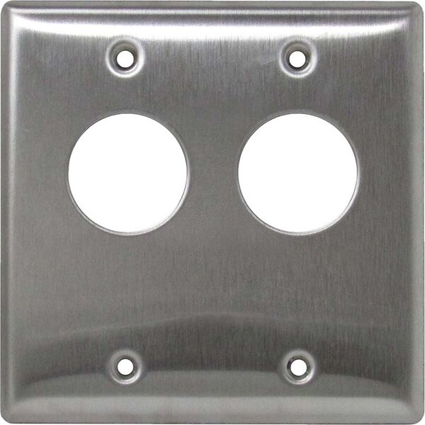
Camden CM-3560 – Key Switch, (2) SPDT Maintained

$75.00

Key Switch, (2) SPDT Maintained

SKU: CM-3560
Category:
Brands:

Description

Series: CM-3200 & CM-3500 Series

Type: Stainless Steel, 2 Gang, Flush Mount

Configuration: Double Gang Dual Cylinder Key Switch

Key Switch, (2) SPDT Maintained

Brand: Camden

Manufacturer Part Number: CM-3560

Source: Camden Controls product page
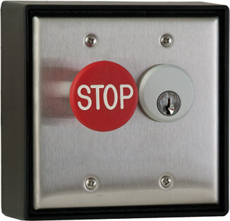
Reviews

There are no reviews yet.

Be the first to review “Camden CM-3560 – Key Switch, (2) SPDT Maintained”

Your email address will not be published. Required fields are marked *

Camden Door Controls CM-3200/3500 Series flush mount key switches meet the demands of key switch controls, designed for use with standard 1", 1-1/8", or 1-1/4" mortise cylinders and accepting one or two cylinders with up to four switches. They are double gang width with heavy duty stainless steel faceplates and control overhead doors, electric locks, electro-magnetic locks, electric strikes, and motors.

Product specifications
Faceplate heavy duty double gang, 18 gauge stainless steel
Input voltage 12-24V AC/DC
Contact rating standard 6 A @ 30VDC
Contact rating optional 15 A @ 30VDC
Lead wire 18 AWG color coded soldered leads
Mortise cylinder size 1", 1-1/8", or 1-1/4"
Switch count up to 4 switches
Included hardware brass cylinder lock ring, 4 socket/slotted screws, 4 tamperproof screws with driver
Dimensions 4-1/2" (114mm) x 4-1/2" (114mm)
Low-voltage wiring Required
BasisStructured, independently qualified product connection evidence
PreparationFit the aluminum bracket against the stud behind the faceplate. Insert the separately purchased mortise cylinder from the front and align its side grooves with the bracket retainers. If irregular grooves prevent fitting, file the retainers slightly; never remove them completely. Tighten the brass cylinder lock ring to secure the bracket. Fit the supplied switch in the selected bracket hole with its spacer ring and threaded washer. Align the cam centrally over the switch and check key operation before fastening the unit to the selected switch box, wall or receptacle box with the supplied screws. Select the mounting arrangement and compatible cylinder for the installation.
ElectricalOfficial model description: Key Switch, (2) SPDT Maintained. The shared manual quantity column and some exact dual-cylinder model descriptions differ; verify the delivered assembly and manufacturer total-versus-per-cylinder interpretation before calculating overall conductors. For each used changeover pole, common plus NO or common plus NC requires two external conductors; common plus both NO and NC requires three. Do not join independent commons by assumption. These are low-voltage circuit conductor counts, not physical cable-run counts. The supplied 18 AWG soldered leads do not specify field cable gauge. Common is grey; momentary NO is blue and NC orange. The maintained-contact chart lists both throw leads orange, so identify the actual terminal function before connecting. Cable type, gauge, shielding and physical run quantities depend on the selected controller/device and site routing. Optional LED circuits remain separate and require their selected DC option instructions. The standard-contact parts table and family specification give different contact ratings; verify the fitted switch rating. Contact ratings are not supply requirements.
Preparation requiredYes
Electrical wiring requiredYes
Conditional connectionsOptional LED indicator circuit: cable runs quantity unspecified; conductor count unspecified; wire type not documented; size unspecified; shielding unspecified; rating unspecified; endpoints optional LED indicator to 12 V or 24 V supply; when Installation configuration is Optional accessory selected: IF an LED indicator option (-70xx, -71xx, -72xx, -74xx or -76xx) is selected. Not part of the base CM-3560. Wiring details are not documented in the supplied text.; Switch contact leads for the two SPDT maintained switches: COMMON (grey), NORMALLY OPEN (orange), NORMALLY CLOSED (orange), as in the SPDT maintained column of the wiring table: cable runs quantity unspecified; conductor count unspecified; wire type not documented; size unspecified; shielding unspecified; rating unspecified; endpoints SPDT maintained switch factory soldered leads to external controlled circuit (not documented); when Installation configuration is Internal accessory connection; not field cable: Base product, CM-3560 with 2 SPDT maintained switches. These are the factory soldered color-coded leads on the switches; the field cable between the leads and the controlled device is not documented. Using NO or NC depends on the application, and not every lead must be used.; Selected base selected switch: common and NO: cable runs quantity unspecified; 2 conductor(s); wire type not documented; size unspecified; shielding unspecified; rating Field cable type, gauge, shielding and physical run quantity unspecified. Supplied18AWG solderedleads do not establish field cable gauge.; endpoints Selected low-voltage controlled equipment to CM-3560 selected switch common and NO; when Installation configuration is For selected switch, select common and NO. This is an alternative pole configuration; do not add it to the other alternatives for the same pole. Repeat for every used switch in the verified delivered assembly; total switch quantity is unresolved. No physical run count is inferred.; Selected base selected switch: common and NC: cable runs quantity unspecified; 2 conductor(s); wire type not documented; size unspecified; shielding unspecified; rating Field cable type, gauge, shielding and physical run quantity unspecified. Supplied18AWG solderedleads do not establish field cable gauge.; endpoints Selected low-voltage controlled equipment to CM-3560 selected switch common and NC; when Installation configuration is For selected switch, select common and NC. This is an alternative pole configuration; do not add it to the other alternatives for the same pole. Repeat for every used switch in the verified delivered assembly; total switch quantity is unresolved. No physical run count is inferred.; Selected base selected switch: common, NO and NC: cable runs quantity unspecified; 3 conductor(s); wire type not documented; size unspecified; shielding unspecified; rating Field cable type, gauge, shielding and physical run quantity unspecified. Supplied18AWG solderedleads do not establish field cable gauge.; endpoints Selected low-voltage controlled equipment to CM-3560 selected switch common, NO and NC; when Installation configuration is For selected switch, select common, NO and NC. This is an alternative pole configuration; do not add it to the other alternatives for the same pole. Repeat for every used switch in the verified delivered assembly; total switch quantity is unresolved. No physical run count is inferred.

Official manufacturer documents