
Description
Series: CM-1000 Series
Type: Cast Aluminum with Surface Box
Surface Mount Key Switch, DPDT Momentary
Brand: Camden
Manufacturer Part Number: CM-1080
Source: Camden Controls product page
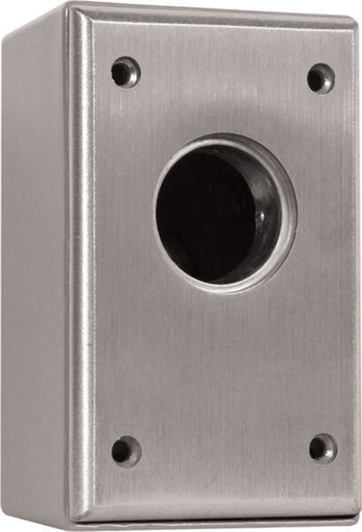
Surface Mount Key Switch, DPDT Momentary
Series: CM-1000 Series
Type: Cast Aluminum with Surface Box
Surface Mount Key Switch, DPDT Momentary
Brand: Camden
Manufacturer Part Number: CM-1080
Source: Camden Controls product page
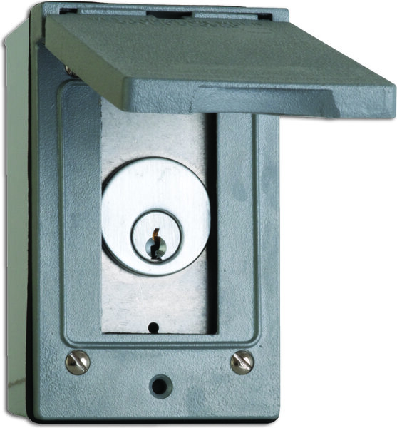
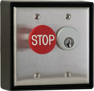
Camden Door Controls, CM-1000 Series surface mount switches meet the stringent demands of key switch controls. They are designed for use with standard 1", 1 1/8", or 1 1/4" mortise cylinders, fabricated from 1/4" thick aluminum into a one-piece die-cast construction. All controls provide for one (1) or two (2) switch configurations.
| Low-voltage wiring | Required |
|---|---|
| Basis | Structured, independently qualified product connection evidence |
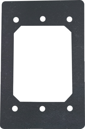
| Preparation | Provide a compatible mortise cylinder, sold separately, and fit it to the supplied faceplate and surface box. Align the cylinder cam with the selected switch and secure the cylinder lock ring. For outdoor installation, place the weatherproof gasket behind the faceplate before securing it to the surface box. |
| Electrical | Base configuration: Surface Mount Key Switch, DPDT Momentary. For each used changeover pole, common plus NO or common plus NC requires two external conductors; common plus both NO and NC requires three. Each DPDT switch contains two independent poles. Do not join independent commons by assumption. These are low-voltage circuit conductor counts, not physical cable-run counts. The supplied 18 AWG soldered leads do not specify field cable gauge. Common is grey; momentary NO is blue and NC orange. The maintained-contact chart lists both throw leads orange, so identify the actual terminal function before connecting. Cable type, gauge, shielding and physical run quantities depend on the selected controller/device and site routing. Optional LED circuits remain separate and require their selected DC option instructions. The standard-contact parts table and family specification give different contact ratings; verify the fitted switch rating. Contact ratings are not supply requirements. |
| Preparation required | Yes |
| Electrical wiring required | Yes |
| Conditional connections | Optional LED indicator circuit (Red, Green or Amber, DC only): cable runs quantity unspecified; conductor count unspecified; wire type not documented; size unspecified; shielding unspecified; rating unspecified; endpoints LED red (+) and black (-) leads to 12 VDC or 24 VDC supply; when Installation configuration is Optional accessory selected: IF an LED indicator option (e.g. -7424 amber 24V for CM-1080) is selected. This is not part of the base product. The LED is DC only; the 24 VDC version uses a 1.5 k ohm resistor in the circuit as shown in Fig. 3. Cable runs are not documented.; Selected base switch 1 pole 1: common and NO: cable runs quantity unspecified; 2 conductor(s); wire type not documented; size unspecified; shielding unspecified; rating Field cable type, gauge, shielding and physical run quantity unspecified. Supplied18AWG solderedleads do not establish field cable gauge.; endpoints Selected low-voltage controlled equipment to CM-1080 switch 1 pole 1 common and NO; when Installation configuration is For switch 1 pole 1, select common and NO. This is an alternative pole configuration; do not add it to the other alternatives for the same pole. Use only the supplied switches/poles needed by the controlled equipment. No physical run count is inferred.; Selected base switch 1 pole 1: common and NC: cable runs quantity unspecified; 2 conductor(s); wire type not documented; size unspecified; shielding unspecified; rating Field cable type, gauge, shielding and physical run quantity unspecified. Supplied18AWG solderedleads do not establish field cable gauge.; endpoints Selected low-voltage controlled equipment to CM-1080 switch 1 pole 1 common and NC; when Installation configuration is For switch 1 pole 1, select common and NC. This is an alternative pole configuration; do not add it to the other alternatives for the same pole. Use only the supplied switches/poles needed by the controlled equipment. No physical run count is inferred.; Selected base switch 1 pole 1: common, NO and NC: cable runs quantity unspecified; 3 conductor(s); wire type not documented; size unspecified; shielding unspecified; rating Field cable type, gauge, shielding and physical run quantity unspecified. Supplied18AWG solderedleads do not establish field cable gauge.; endpoints Selected low-voltage controlled equipment to CM-1080 switch 1 pole 1 common, NO and NC; when Installation configuration is For switch 1 pole 1, select common, NO and NC. This is an alternative pole configuration; do not add it to the other alternatives for the same pole. Use only the supplied switches/poles needed by the controlled equipment. No physical run count is inferred.; Selected base switch 1 pole 2: common and NO: cable runs quantity unspecified; 2 conductor(s); wire type not documented; size unspecified; shielding unspecified; rating Field cable type, gauge, shielding and physical run quantity unspecified. Supplied18AWG solderedleads do not establish field cable gauge.; endpoints Selected low-voltage controlled equipment to CM-1080 switch 1 pole 2 common and NO; when Installation configuration is For switch 1 pole 2, select common and NO. This is an alternative pole configuration; do not add it to the other alternatives for the same pole. Use only the supplied switches/poles needed by the controlled equipment. No physical run count is inferred.; Selected base switch 1 pole 2: common and NC: cable runs quantity unspecified; 2 conductor(s); wire type not documented; size unspecified; shielding unspecified; rating Field cable type, gauge, shielding and physical run quantity unspecified. Supplied18AWG solderedleads do not establish field cable gauge.; endpoints Selected low-voltage controlled equipment to CM-1080 switch 1 pole 2 common and NC; when Installation configuration is For switch 1 pole 2, select common and NC. This is an alternative pole configuration; do not add it to the other alternatives for the same pole. Use only the supplied switches/poles needed by the controlled equipment. No physical run count is inferred.; Selected base switch 1 pole 2: common, NO and NC: cable runs quantity unspecified; 3 conductor(s); wire type not documented; size unspecified; shielding unspecified; rating Field cable type, gauge, shielding and physical run quantity unspecified. Supplied18AWG solderedleads do not establish field cable gauge.; endpoints Selected low-voltage controlled equipment to CM-1080 switch 1 pole 2 common, NO and NC; when Installation configuration is For switch 1 pole 2, select common, NO and NC. This is an alternative pole configuration; do not add it to the other alternatives for the same pole. Use only the supplied switches/poles needed by the controlled equipment. No physical run count is inferred. |


Reviews
There are no reviews yet.