Schlage PB405 Series Power Bolt | Mortise Right Angle Deadbolt

$75.00

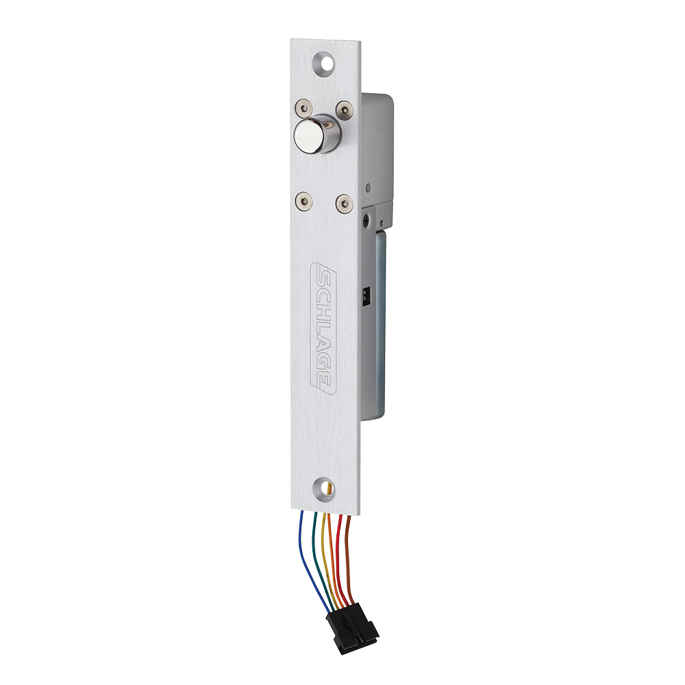
The PB405 PowerBolt is a mortise deadbolt that can be installed in the door frame to provide electronic access control to doors with minimum visual impact.

SKU: SCH-PB405-SERIES-POWER-BOLT
Category:
Brands:

Description

The PB405 PowerBolt is a mortise deadbolt that can be installed in the door frame to provide electronic access control to doors with minimum visual impact.

Brand: Schlage

Manufacturer Part Number: SCH-PB405-SERIES-POWER-BOLT

Source: Official product page

Additional information

voltage

12/24VDC

Reviews

There are no reviews yet.

Be the first to review “Schlage PB405 Series Power Bolt | Mortise Right Angle Deadbolt”

Your email address will not be published. Required fields are marked *

The PB405 PowerBolt is a mortise, right-angle electromechanical deadbolt with a 0.61" diameter bolt and 0.67" throw, available in fail-safe (PB405) or fail-secure (PB405S) versions. It installs in the door frame, includes a built-in door position switch and field-configurable relock delay, and is used for electronic access control of doors, cabinets, and drawers.

Product specifications
Models PB405 (fail-safe), PB405S (fail-secure)
Voltage 12 or 24 VDC, field selectable
Current @ 12 VDC 925 mA starting; 334 mA holding
Current @ 24 VDC 472 mA starting; 193 mA holding
Door position switch SPDT, 0.5A @ 30 VDC
Bolt diameter 0.61 in
Bolt throw 0.67 in
Dimensions 7-7/8"L x 1-1/4"W x 1-5/8"D
Relock timer delay field-selectable: 0, 3, 6, or 9 seconds
Finish satin aluminum (strike plate and mortise face)
Features door position switch; built-in re-locking option; MOV surge protection (PB405S)
Low-voltage wiring Connection count needs review
PreparationThe lock is installed in a prepared area of the door frame, in the top or the side. Steps in the instructions are to check door and frame dimensions, verify bolt throw, determine the installation position, affix templates and prepare the frame (per the template), install the strike plate in the prepared area, and install the lock in the prepared area. Shims are installed for metal doors. Exact cutout dimensions are on the template and are not reproduced in the supplied text.
ElectricalThe lock needs 12 or 24 VDC power (field selectable). It is released by a dry contact from an access control system or switch. The lock body carries six colour-coded leads: brown, red, orange, yellow (NO), green (COM), blue (NC). Per the diagram, the power supply and release contact connect to leads A and B, and the door position switch uses leads D, E and F. Lead C (orange) is not shown connected. The instructions also show an optional 2-wire fail-safe configuration, but its terminal detail is not legible in the supplied text.
Preparation requiredYes
Electrical wiring requiredYes
Conditional connections12 or 24 VDC power supply to lock, with release switched by a dry contact (normally open or normally closed contact per the diagram): cable runs quantity unspecified; conductor count unspecified; wire type not documented; size unspecified; shielding unspecified; rating unspecified; endpoints 12/24 VDC power supply to release dry contact to PB405 lock leads A and B; when Installation configuration is Base product, typical 3-wire fail-safe or fail-secure configuration. Use a normally open contact to release in one diagram and a normally closed contact in the other. Field cable run count and conductor count are not stated.; Door position switch (SPDT) leads: cable runs quantity unspecified; conductor count unspecified; wire type not documented; size unspecified; shielding unspecified; rating unspecified; endpoints PB405 leads D yellow (NO), E green (COM), F blue (NC) to external monitoring device (not specified); when Installation configuration is Base product has a built-in door position switch (SPDT, 0.5 A at 30 VDC). Whether the leads are connected to field cable is not documented. The diagram shows them as bracketed lead ends.

Official manufacturer documents