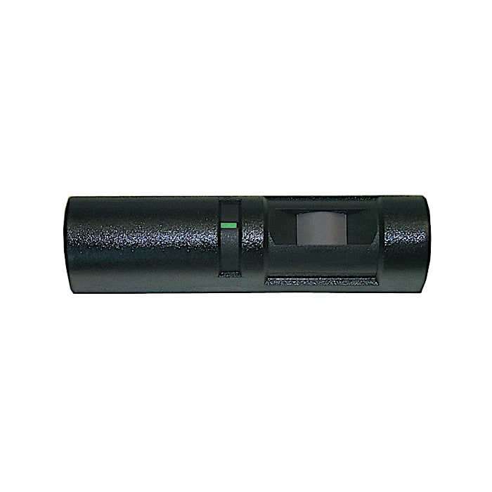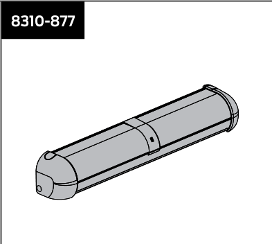
LCN 8310-877 – Header Mount Safety Sensor (HMSS)

$110.00

Model 8310-877. Installer-grade door mount safety sensor.

SKU: 8310-877
Category:
Tags: , ,
Brands:

Description

Safety Sensor, \’Diffused Infrared\’
Technology
Used to detect obstructions
during door open and door closed
position
Nine selectable patterns
8310-859 Handheld Remote
Control required to program 8310-
877 sensor from a distance
Includes 8310-846 Harness
Additional information

Brand

LCN

Reviews

There are no reviews yet.

Be the first to review “LCN 8310-877 – Header Mount Safety Sensor (HMSS)”

Your email address will not be published. Required fields are marked *

LCN 8310 Series is a modular system of touchless and push-plate door actuators, wireless transmitter/receiver sets, mounting boxes, escutcheons, weather/trim rings, safety sensors, and accessory kits used to remotely actuate LCN automatic swing-door operators (e.g., 4630/4640, 7900 pneumatic auto-equalizer, 9100 Benchmark, Senior Swing 2800/9500, Mid Swing 2900/9700 series). Touchless actuators and hardwired push plates require a wired, low-voltage power/control connection back to the door operator control box; most are also compatible with a 433 MHz or 900 MHz wireless transmitter/receiver pair for wireless actuation signaling instead of a run of activation wire. A subset of push plates (8310-852WP/853WP) are fully wireless/battery powered with no field control wiring at the plate itself (only the receiver, sold separately, is wired to the operator).

Product specifications
Touchless actuator supply (8310-813) 12-24 VAC ±10% or 12-24 VDC +30%/-10%, SELV-compatible power supplies only; power consumption < 1.5W; output is a voltage-free relay (max 60VDC/125VAC, 1A resistive, 30W)
900 MHz receiver input voltage (8310-880) 12-24 VAC/VDC; relay contact rating 1.0A@30VDC, 0.3A@60VDC, 0.5A@125VAC
Wireless transmitter power consumption (900 MHz) 30mA (standard TX) / 40mA (RX) / 22mA (retrofit TX)
Receiver capacity up to 74-75 transmitters per standard receiver; unlimited for 'universal' mode
Low-voltage wiring Required
BasisStructured, independently qualified product connection evidence
PreparationPrepare the sensor mounting position on the header/frame and align the harness route. Use the supplied mounting screws; where wiring passes directly through the header, the manual specifies a1/2-inch passage beside the left end cap. Fit the HMSS spacer when the reveal is under3inches or door-mounted safety sensors are also used. Confirm the actual reveal and sensor arrangement before drilling.
ElectricalLow-voltage wiring is required. The8310-877 manufacturer specification calls for12-24VAC/VDC (+/-10%). For the illustrated compatible SeniorSwing controller, use the supplied sensor harness: white10-position plug at the sensor, black6-position plug at controllerP1; do not use the crossed-out7-terminal connector. That supplied harness has six conductors in one supplied cable assembly. Its length is shown in the manufacturer specifications. This is one supplied harness per sensor, not a count of additional cable pulls or all system wiring. For other operators, follow the matching controller diagram before cutting off the controller plug. Gauge and shielding are not specified in this manual. Monitoring must follow the selected interface instructions; connector position count is not a conductor count.
Preparation requiredYes
Electrical wiring requiredYes
Conditional connectionsSafety module harness for pneumatic control box (via the 8310-3889 safety module kit): cable runs quantity unspecified; conductor count unspecified; wire type not documented; size unspecified; shielding unspecified; rating unspecified; endpoints 8310-877 header mount safety sensor to Pneumatic control box (7901, 7902, 7981, 7982); when Installation configuration is Optional accessory selected: IF accessory selected: the 8310-3889 kit is required when the 8310-877 is used with pneumatic automatic operators. The kit includes the 8310-3888 safety module harness. The exact wiring is not documented in the supplied text.; Supplied low-voltage877-to-SeniorSwing harness: cable runs 1; 6 conductor(s); wire type Manufacturer-supplied header-sensor harness. Gauge and shielding not specified.; size unspecified; shielding unspecified; rating Manufacturer-supplied header-mount harness; six conductors, one4ft cable assembly per sensor. Gauge/shielding not specified. Use the actual controller diagram75.5546 and compatible harness; additional site runs are separate.; endpoints 8310-877 white10-position sensor connector to Compatible SeniorSwing controllerP1 black6-position connector; when Installation configuration is Only the supplied header-sensor harness and compatible SeniorSwing P1 interface illustrated on original877 manual page5. One physical supplied harness assembly per sensor, with six populated conductors. Not the crossed-out7-terminal connector, not other controllers, not additional field cable pulls or a whole-system conductor total.

Official manufacturer documents