
Description
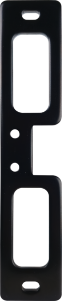
The low-profile, surface mounted electric strike designed to accommodate the Adams Rite 8700 and 8800 Series Rim Exit Devices.
Brand: HES
Category: Electric Strikes
List Price Range: $708 – $1,133
Source: HES product page
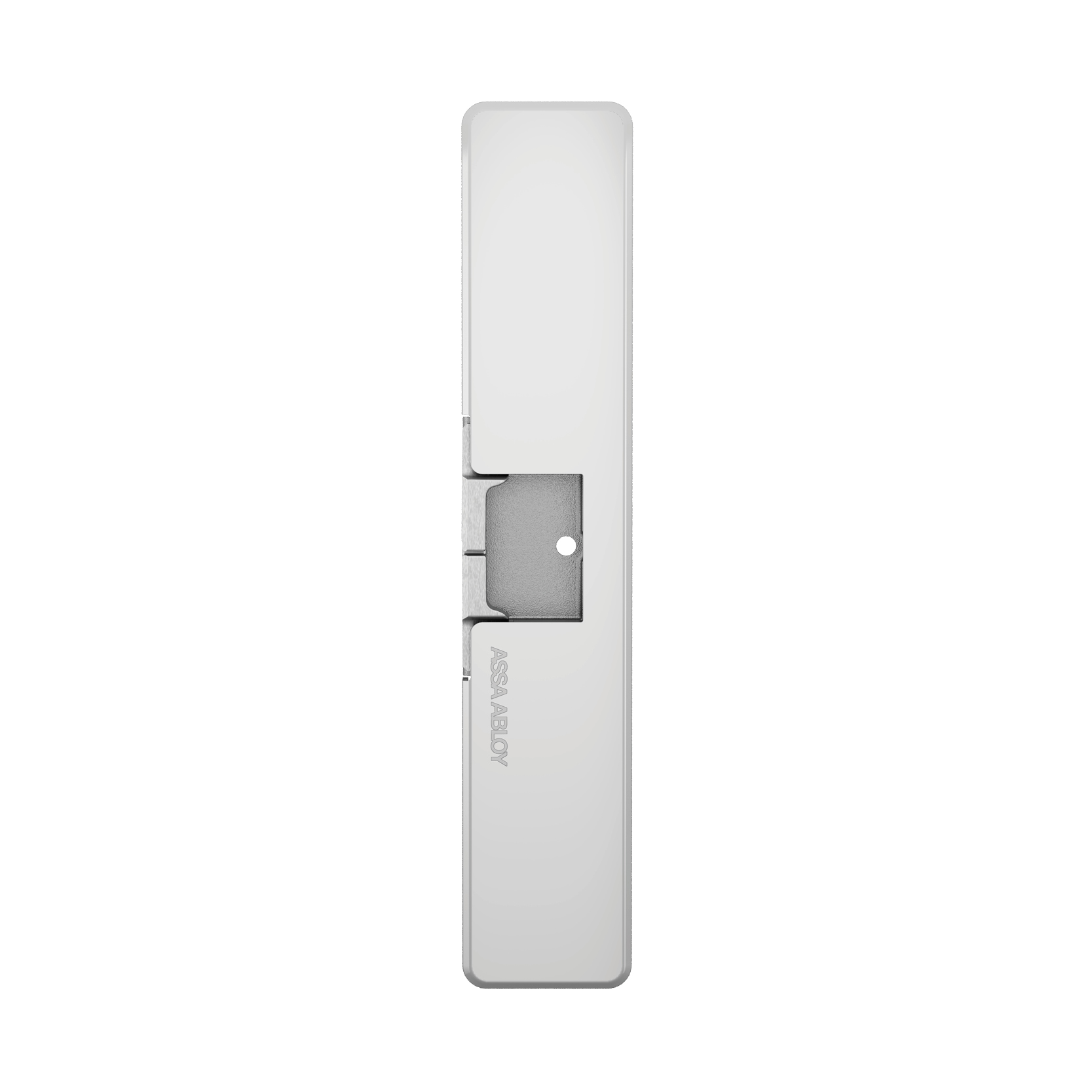
The low-profile, surface mounted electric strike designed to accommodate the Adams Rite 8700 and 8800 Series Rim Exit Devices.
The low-profile, surface mounted electric strike designed to accommodate the Adams Rite 8700 and 8800 Series Rim Exit Devices.
Brand: HES
Category: Electric Strikes
List Price Range: $708 – $1,133
Source: HES product page
| finish | 605, 606, 612, 613, 629, 630 |
|---|
The HES 9800 Series is a low-profile, surface-mounted electric strike designed to accommodate the Adams Rite 8800 & 8700 Series rim exit devices.
| Voltage | 12/24 |
|---|---|
| Body Material | Stainless steel |
| Static Strength (lbs) | 1,500 |
| Dynamic Strength (ft-lbs) | 70 |
| Endurance (cycles) | 1,000,000 |
| Fail Safe | Fail Secure | Field selectable fail safe/fail secure |
| Monitoring Installation | Factory Configured |
| Monitoring Options | Latchbolt Monitoring|Latchbolt Strike Monitor |
| Lock Type | Exit Device |
| Adjustability | Horizontal |
| Surface Mounting | Yes |
| Frame Material | Aluminum|Metal|Wood |
| Latchbolt Accommodation | Starwheel/Interlock (compatible with Adams Rite 8700/8800 Series Rim Exit Devices) |
| Strike Body Depth (in) | 0.5625 |
| Strike Body Height (in) | 9 |
| Included in Box | 9800 Electric Strike Body, 9800 Cover, 1/4"-20 x 1" Mounting Screws, #10-32 & 10-24 Lockdown Screws (optional), #6-32 x 1/4" Cover Screws, 5/64" Hex Key, 12 & 24 Volt Plug In Connectors |
| Low-voltage wiring | Required |
| Basis | Structured, independently qualified product connection evidence |
| Preparation | Mark the latchbolt centerline and the appropriate frame holes from the manufacturer template, then punch, drill and tap the marked holes as required. Check latchbolt engagement and clearance before final tightening. An aluminum frame with a blade stop requires the separately sold HES 9000-ASB; use its own installation instructions and account for the retrofit offset. |
| Electrical | Continuous-duty solenoid voltage: 12 VDC or 24 VDC. Use the plug-in connector marked for the selected system voltage and verify input voltage with a multimeter before connection. Select the actual fail-secure or fail-safe configuration and wire optional monitoring circuits separately. |
| Preparation required | Yes |
| Electrical wiring required | Yes |
| Conditional connections | Latchbolt Monitor (LBM) switch wiring (9800 only): cable runs quantity unspecified; conductor count unspecified; wire type not documented; size unspecified; shielding unspecified; rating unspecified; endpoints LBM switch (white common, orange NC, green NO) to Access control system or panel; when Installation configuration is Optional accessory selected: Optional accessory selected: Only if LBM is fitted on the9800. The white common, orange NC and green NO labels are the Table1 reference state with the door CLOSED. The shared manual shows the opposite contact state with LBM unactuated and the door OPEN. Contact rating500mA at30V. Separate from solenoid power; select the actual monitor input.; Latchbolt Strike Monitor (LBSM) switch wiring (9800 only): cable runs quantity unspecified; conductor count unspecified; wire type not documented; size unspecified; shielding unspecified; rating unspecified; endpoints LBSM brown common; blue/yellow NO/NC assignment unresolved to Selected access-control monitor input; when Installation configuration is Optional accessory selected: Optional accessory selected: Only if LBSM is fitted on the9800. Brown is common. The manufacturer PDF page4 Table1 and Diagram5 disagree about the blue/yellow NO/NC roles in the unpowered strike state. Those role assignments remain unknown: verify the matching manufacturer revision and actual unit before connecting this monitor. Contact rating500mA at30V. Separate from solenoid power.; DC solenoid power: cable runs quantity unspecified; 2 conductor(s); wire type not documented; size unspecified; shielding unspecified; rating Match the manufacturer voltage and duty specifications; size actual conductors using the installation-specific length/current table. Nonnumeric installation context (does not broaden the selected count): Select the manufacturer connector for the chosen voltage. Internal series/parallel coil conversion links are part of the strike wiring arrangement and do not establish a total field-cable count. 12 VDC or 24 VDC, matching the selected connector.; endpoints External power supply and selected control contact to HES 9800 selected voltage-matched strike power-input connector; when Installation configuration is 9800 only, selected12/24VDC fail-secureNO branch at external strike power interface. No inference aboutAdams Rite7800 variants. Two conductors terminate at the strike power interface only. Internal coil links, optional monitors, earth and field cable/run/jacket quantities are excluded. This is not a universal total for other configurations.; Optional latchbolt monitoring: cable runs quantity unspecified; conductor count unspecified; wire type not documented; size unspecified; shielding unspecified; rating unspecified; endpoints Selected LBM or LBSM switch leads to Selected access-control monitor input; when Installation configuration is Optional accessory selected: Optional accessory selected: Only if the corresponding monitor is fitted. With LBM unactuated and door OPEN, the shared manufacturer manual shows white common, orange NO and green NC; the door-CLOSED Table1 reference state reverses those LBM contact states. LBSM brown common is supported, but the blue/yellow NO/NC assignments remain unknown because the exact9800 manual Table1 disagrees with its Diagram5 for an unpowered strike. Verify the matching manufacturer revision and actual unit before connecting LBSM. Factory leads do not specify a field conductor count. |

Reviews
There are no reviews yet.