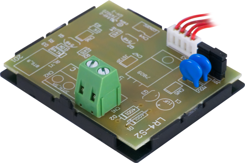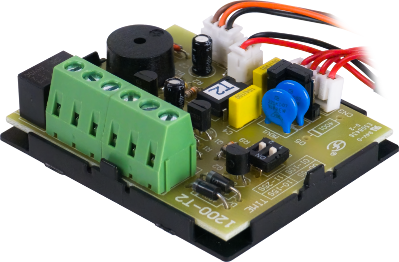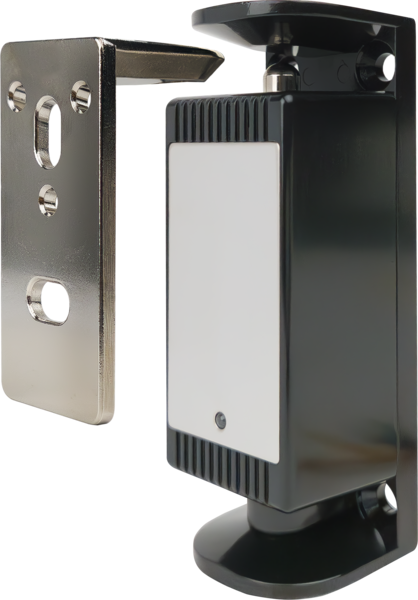
CX-ED0010 – CX-ED0010: Electromechanical Cabinet Lock

CX-ED0010: Electromechanical Cabinet Lock – Camden Door Controls

SKU: CX-ED0010
Category: , , ,
Brands:

Description

CX-ED0010: Electromechanical Cabinet Lock – Camden Door Controls

Source: https://www.camdencontrols.com/category/locking/Cabinet_Locks/products/CX_ED0010

Resources:
https://www.camdencontrols.com/pipelines/resource/36211_CX_ED0010_Spec_Sheet.pdf
https://www.camdencontrols.com/pipelines/resource/36212_66ODWWOKK6IPWWQC2YC4.pdf
https://www.camdencontrols.com/pipelines/resource/36213_CX_ED0010_Spec_Sheet_FR.pdf
https://www.camdencontrols.com/pipelines/resource/36214_ZK5VB7FPHSIKQ8DIVACK.pdf
https://www.camdencontrols.com/pipelines/resource/36215_CX_ED0010_Spec_Sheet_SP.pdf
https://www.camdencontrols.com/pipelines/resource/36216_5PBATQMTVHGCY7VW7JTC.pdf
https://www.camdencontrols.com/pipelines/resource/36207_CX_ED0010_Electromechanical_Cabinet_Lock_Manual_FR.pdf
https://www.camdencontrols.com/pipelines/resource/36208_CFLU63JWERWE9RWIOR57.pdf
https://www.camdencontrols.com/pipelines/resource/36209_CX_ED0010_Electromechanical_Cabinet_Lock_Manual_R1.pdf
https://www.camdencontrols.com/pipelines/resource/36210_UPT1HX82ZP0YR5QEVAGM.pdf
https://www.camdencontrols.com/pipelines/resource/36219_Camden_Cabinet_Lock_Solutions.pdf
https://www.camdencontrols.com/pipelines/resource/36220_J4GSDIZXOPBM3XPZDTAC.pdf

Reviews

There are no reviews yet.

Be the first to review “CX-ED0010 – CX-ED0010: Electromechanical Cabinet Lock”

Your email address will not be published. Required fields are marked *

Camden's CX-ED0010 Electromechanical Cabinet Lock is designed for enclosures with swinging doors, drawers, and sliding doors (e.g. computer cabinets, lockers, retail display counters, medical/cannabis dispensaries), supporting both 12V and 24V power with field-selectable fail-safe or fail-secure operation. It includes door and lock status sensors, a strike plate that adjusts to door alignment, and provides 440 lbs (200 kg) holding force.

Product specifications
Power input 12 / 24 VDC
Current draw 280mA @ 12VDC, 140mA @ 24VDC
Contact rating 200mA @ 30VDC (Max) Form 'C'; 1A @ 30V DC (Max)
Endurance 250,000 Cycles (door status sensor)
Holding force 440 lbs (200 kg)
Temperature -4°F to 140°F (-20°C to 60°C)
Operation mode Field Selectable Fail-Safe or Fail-Secure
Dimensions Lock body: 3-5/16"H x 1-3/16"W x 1-1/8"D (84mm x 30mm x 28mm); Strike plate: 2-1/2"H x 27/32"W x 1-1/4"D (64mm x 21.5mm x 31.6mm)
Low-voltage wiring Connection count needs review
PreparationThe lock body and strike plate are mounted on the frame/cabinet body and the door/drawer. Mounting locations are marked and pilot holes are drilled. The supply voltage jumper is set before installation (12 VDC default, 24 VDC by closing PIN-3 and PIN-4 only). The lock mode is selected (fail-secure default, or fail-safe by repositioning the chassis). The door status sensor is placed in a mode-dependent slot, and the cover plate is attached after the input power setting.
ElectricalThe lock is powered at 12 or 24 VDC through its red (+) and black (-) leads, and the instructions say to wire it per the chosen wiring diagram (A-D). The sensor outputs (LSS blue/green/white, DSS orange/white) are separate relay-contact outputs. The yellow LED wire is used only in the LED-related diagrams. The documents give no field cable gauge and no cable run count.
Preparation requiredYes
Electrical wiring requiredYes
Conditional connectionsDC power supply to lock (red +, black -): cable runs quantity unspecified; conductor count unspecified; wire type not documented; size unspecified; shielding unspecified; rating unspecified; endpoints 12 VDC/24 VDC power supply to lock red (+) and black (-) leads; when Installation configuration is Base product, all wiring diagrams A-D. The input voltage jumper must match the supply (12 V default, 24 V with PIN-3 and PIN-4 only closed). Whether the leads are factory pigtails or field cable is not documented.; Lock status sensor relay contact output (blue NO, green NC, white COM): cable runs quantity unspecified; conductor count unspecified; wire type not documented; size unspecified; shielding unspecified; rating unspecified; endpoints lock status sensor relay contacts to external monitoring device; when Installation configuration is Optional accessory selected: IF the lock status output is used. It is a separate signal circuit from power, rated 200mA@30VDC max, Form C. Which terminals are used depends on the external device.; Door status sensor relay contact output (orange NO, white COM): cable runs quantity unspecified; conductor count unspecified; wire type not documented; size unspecified; shielding unspecified; rating unspecified; endpoints door status sensor relay contacts to external monitoring device; when Installation configuration is Optional accessory selected: IF the door status output is used. The orange wire changes state only when the door status sensor (magnet) is attached to the strike plate. This is separate from power.; LED indication wiring (yellow wire): cable runs quantity unspecified; conductor count unspecified; wire type not documented; size unspecified; shielding unspecified; rating unspecified; endpoints yellow LED wire to +ve supply; when Installation configuration is Optional accessory selected: IF the LED indication is used in the fail-secure configurations (A/B). The LED is covered in fail-safe diagrams C and D. The yellow wire is connected to +ve in the diagrams that use it.

Official manufacturer documents