
Description
Series: CX-WC Series
Type: Barrier Free Restroom Control
Touchless Switch Restroom Kit
Brand: Camden
Manufacturer Part Number: CX-WC16-PS
Source: Camden Controls product page
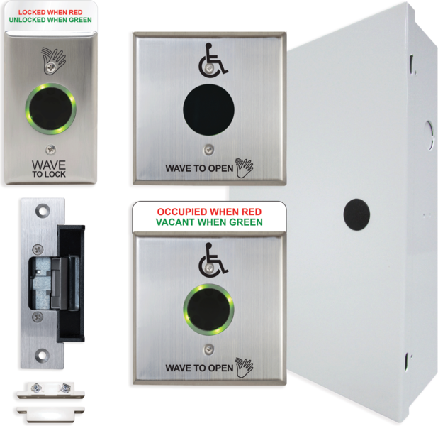
Touchless Switch Restroom Kit
Series: CX-WC Series
Type: Barrier Free Restroom Control
Touchless Switch Restroom Kit
Brand: Camden
Manufacturer Part Number: CX-WC16-PS
Source: Camden Controls product page
| mount | flush, surface |
|---|
| Low-voltage wiring | Connection count needs review |
|---|---|
| Preparation | Documented site prerequisites are a suitable cabinet location and prepared mounting boxes for the touchless switches. The switches are mounted in single gang, double gang or 4×4 electrical boxes, either in-wall or surface mount. In-wall boxes must be plumb, square and flush with the wall surface; surface boxes must be secure and plumb. The kit's 4×4 box adaptor plate is included in the packages. Power must not be applied until the instructions are read and the adjustments (DIP switches, range and time potentiometers, mode) are made. |
| Electrical | The kit is a wired system. The cabinet's CX-33 controller is pre-wired to labelled terminal strips (left strip for power and inputs, right strip for strike, door operator, light ring and strike power). Field devices are wired to those strips, and the supplied CX-TRX-5024 transformer secondary is wired to the AC terminals, with the primary wired to the AC feed. The wiring of the physical devices is documented in prose. Cable run counts and conductor counts per run are not documented, so they remain unknown. |
| Preparation required | Yes |
| Electrical wiring required | Yes |
| Conditional connections | AC supply to the supplied CX-TRX-5024 transformer primary (the transformer secondary goes to the AC terminals of the left terminal strip): cable runs quantity unspecified; conductor count unspecified; wire type not documented; size unspecified; shielding unspecified; rating unspecified; endpoints AC feed to CX-TRX-5024 transformer primary; when Installation configuration is Base kit, power readiness; the supply wiring for the transformer is site work; Inside Wave to Open sensor (CM-325/42WS): two red wires for power (not polarity sensitive), blue (NO) and green (common) to CX-33 Dry2 & Input: cable runs quantity unspecified; conductor count unspecified; wire type not documented; size unspecified; shielding unspecified; rating unspecified; endpoints CM-325/42WS inside Wave to Open to CX-33 Dry2 & Input; when Installation configuration is Base kit, field device wiring; the red, blue and green wires are the sensor's device leads, so the field cable count is not established; Strike output (Relay 1) and VDC power for the door strike from the right terminal strip; optional door operator output (Relay 2) and the door position switch and Wet trigger on the left strip: cable runs quantity unspecified; conductor count unspecified; wire type not documented; size unspecified; shielding unspecified; rating unspecified; endpoints CX-33 right terminal strip Relay 1 and VDC output to Electric strike to Door position switch (left strip); when Installation configuration is Base kit, strike and door contact are in the kit; the door operator (Relay 2) output applies only IF a door operator is used. Cable counts are not established; Transformer secondary to cabinet AC terminals (power supply for the CX-33 and cabinet): cable runs quantity unspecified; conductor count unspecified; wire type not documented; size unspecified; shielding unspecified; rating unspecified; endpoints CX-TRX-5024 transformer secondary to Left terminal strip AC terminals; when Installation configuration is Base kit as supplied with the CX-TRX-5024 transformer. The primary is wired to the site AC feed, and the manual does not state the conductor count or cable gauge.; Outside WAVE TO OPEN sensor (CM-331/42WS-SGLR): power input: cable runs quantity unspecified; conductor count unspecified; wire type not documented; size unspecified; shielding unspecified; rating unspecified; endpoints Sensor TB1 12/24V power terminals to Left terminal strip; when Installation configuration is Base kit. Power is 12/24 VAC/VDC and not polarity sensitive. Cable run count is not documented.; Outside WAVE TO OPEN sensor: N.O. relay output to Dry1/Input on the CX-33: cable runs quantity unspecified; conductor count unspecified; wire type not documented; size unspecified; shielding unspecified; rating unspecified; endpoints Sensor TB3 relay common and N.O. to CX-33 Dry1 and Input (Outside Push To Open terminals); when Installation configuration is Base kit, outside sensor control signal. The cable run is separate from power, and the count is not documented.; Inside WAVE TO OPEN sensor (CM-325/42WS): power and relay output: cable runs quantity unspecified; conductor count unspecified; wire type not documented; size unspecified; shielding unspecified; rating unspecified; endpoints Sensor two red wires (power) to Sensor blue (N.O.) and green (common) wires to CX-33 Dry2 and Input; when Installation configuration is Base kit. The manual describes the sensor leads and their destinations, but the number of field cable runs is not stated. The sensor's own leads are not field cable cores.; Inside WAVE TO LOCK sensor (CM-331/43S-SGLR): power and N.O. relay output to Dry3/Input: cable runs quantity unspecified; conductor count unspecified; wire type not documented; size unspecified; shielding unspecified; rating unspecified; endpoints Sensor TB1 power to Sensor TB3 relay common and N.O. to CX-33 Dry3 and Input (Push To Lock terminals); when Installation configuration is Base kit. Cable run and conductor counts are not documented, other than the mounting text mentioning a 4 or 6-conductor wire for the SureWave device installation.; Electric strike control and power from the right terminal strip (Relay 1, strike VDC): cable runs quantity unspecified; conductor count unspecified; wire type not documented; size unspecified; shielding unspecified; rating unspecified; endpoints Right terminal strip +Strike / -Strike to Universal electric strike; when Installation configuration is Base kit, strike supplied in the kit. Mode 7 corresponds to fail safe and Mode 8 to fail secure. The manual's diagram example shows a CX-ED2079 strike, but the kit's strike is a universal strike, so the strike model on the diagram is not treated as the kit's strike. The cable run count is not documented.; Door position switch (magnetic contact) to the DPS terminals: cable runs quantity unspecified; conductor count unspecified; wire type not documented; size unspecified; shielding unspecified; rating unspecified; endpoints Door position switch to Left terminal strip DPS NC / DPS COMM; when Installation configuration is Base kit, the magnetic contact is supplied. Per the diagram the contact is connected directly to the DPS terminals if no Emergency Call System is installed. The run count is not documented.; Door operator output (Relay 2) from the right terminal strip: cable runs quantity unspecified; conductor count unspecified; wire type not documented; size unspecified; shielding unspecified; rating unspecified; endpoints Right terminal strip Door Operator terminals to Automatic door operator; when Installation configuration is Optional accessory selected: IF a door operator is installed. The kit contents do not include a door operator, and the terminals are provided for it. The run count is not documented. |

Reviews
There are no reviews yet.