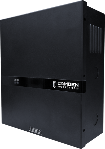
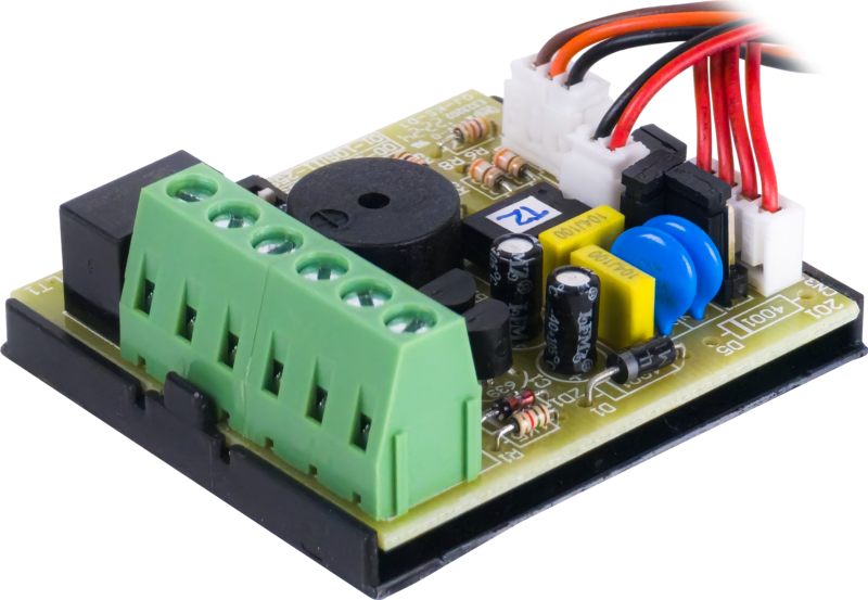
Camden CX-PS150UL – 1.7A power supply, (2) fused outputs 2A, 12/24VDC

$60.00

1.7A power supply, (2) fused outputs 2A, 12/24VDC, UL294/ULC S533 Variant record generated from manufacturer nomenclature (https://www.camdencontrols.com/products/CX_PS_Series); price inherited from product #3038 pending owner confirmation.

Brands:

Description

1.7A power supply, (2) fused outputs 2A, 12/24VDC, UL294/ULC S533 Variant record generated from manufacturer nomenclature (https://www.camdencontrols.com/products/CX_PS_Series); price inherited from product #3038 pending owner confirmation.
Reviews

There are no reviews yet.

Be the first to review “Camden CX-PS150UL – 1.7A power supply, (2) fused outputs 2A, 12/24VDC”

Your email address will not be published. Required fields are marked *

Product specifications
Low-voltage wiring Required
BasisStructured, independently qualified product connection evidence
PreparationMount the cabinet using its four mounting holes in a protected indoor controlled environment. Keep low-voltage wiring separate from AC wiring. Select the required output voltage using JV: OFF for 12VDC, ON for 24VDC. Measure output voltage before connecting the magnetic lock or electric strike. Secure the cabinet door with the supplied screw.
ElectricalLow-voltage field wiring is required for the selected load and control circuits. The magnetic lock connects to +MAG LOCK and -COM; an electric strike connects to +STRIKE and -COM. Each selected lock circuit requires two conductors. Optional AUX+/- power, FIRE/ACP TRIGGER and RESET interfaces each use two conductors in the documented configurations. Select NO or NC triggering and fit the 2.2K Ohm end-of-line resistor at the remote FACP/ACP; the reset option uses the resistor at its key switch or push button. JL OFF requires reset after the trigger clears; JL ON follows the trigger. Keep power-limited and non-power-limited wiring at least 0.25 inch apart. Field cable-run quantities, cable type, gauge and shielding require the connected-device specifications and site routing.
Preparation requiredYes
Electrical wiring requiredYes
Conditional connections120 VAC mains input to the AC input fuse terminal block: cable runs quantity unspecified; conductor count unspecified; wire type not documented; size unspecified; shielding unspecified; rating unspecified; endpoints 120 VAC mains via dedicated disconnect to AC Input Fuse Terminal Block; when Installation configuration is Base product mains power: Ground/Earth, Neutral and Live leads are connected with correct phase and polarity; maximum 15 A branch protection through a readily accessible disconnect.; DC power to a magnetic lock: cable runs quantity unspecified; 2 conductor(s); wire type not documented; size unspecified; shielding unspecified; rating Physical cable-run quantity, cable type, gauge and shielding are unspecified; select for connected equipment and site routing.; endpoints + Mag Lock and -COM terminals to Magnetic lock; when Installation configuration is IF a magnetic lock is the locking device: connect positive polarity to + Mag Lock and negative to -COM. It is an alternative to the electric strike connection on the other output.; DC power to an electric strike: cable runs quantity unspecified; 2 conductor(s); wire type not documented; size unspecified; shielding unspecified; rating Physical cable-run quantity, cable type, gauge and shielding are unspecified; select for connected equipment and site routing.; endpoints +STRIKE and -COM terminals to Electric strike; when Installation configuration is IF an electric strike is the locking device: connect positive polarity to +STRIKE and negative to -COM. It is an alternative to the magnetic lock connection on the other output.; Standby battery: cable runs quantity unspecified; conductor count unspecified; wire type not documented; size unspecified; shielding unspecified; rating unspecified; endpoints Battery +/- terminals to 12 VDC sealed lead-acid or gel cell battery, 1-4 Ah; when Installation configuration is Internal accessory connection; not field cable: Optional accessory selected: IF a standby battery is installed (optional, not included); it sits inside the same enclosure. The battery must match the selected output voltage per the voltage selection chart.; Request Access input: cable runs quantity unspecified; conductor count unspecified; wire type not documented; size unspecified; shielding unspecified; rating unspecified; endpoints Request Access terminals to Access request contact; when Installation configuration is Optional accessory selected: IF a request-access contact is used: shorting this input unlocks the maglock or electric strike.; Fire alarm or access control panel trigger input: cable runs quantity unspecified; 2 conductor(s); wire type not documented; size unspecified; shielding unspecified; rating Physical cable-run quantity, cable type, gauge and shielding are unspecified; select for connected equipment and site routing.; endpoints FACP or ACP NO/NC output to FIRE/ACP TRIGGER terminals; when Installation configuration is Optional accessory selected: Optional accessory selected: IF a fire alarm control panel or access control panel interface is used: connect its NO or NC output to the FIRE/ACP TRIGGER terminals and install the provided 2.2K ohm EOL resistor at the panel.; Reset/REX input from key switch or push button: cable runs quantity unspecified; 2 conductor(s); wire type not documented; size unspecified; shielding unspecified; rating Physical cable-run quantity, cable type, gauge and shielding are unspecified; select for connected equipment and site routing.; endpoints Key switch or push button to RESET/REX input; when Installation configuration is Optional accessory selected: Optional accessory selected: IF the latch/reset option is used (jumper JL removed): install the provided 2.2K ohm resistor at the key switch or push button.; Auxiliary 12/24 VDC output to power access devices: cable runs quantity unspecified; 2 conductor(s); wire type not documented; size unspecified; shielding unspecified; rating Physical cable-run quantity, cable type, gauge and shielding are unspecified; select for connected equipment and site routing.; endpoints AUX+/- terminals to Access device; when Installation configuration is Optional accessory selected: Optional accessory selected: IF an access device is powered from the auxiliary output (200 mA); the output is not affected by fire alarm triggering, access request or reset switch.