
Description
Stand-alone prox reader & keypad, 1 relay, 20000 users Variant record generated from manufacturer nomenclature (https://www.camdencontrols.com/products/CV_550_SPK); price inherited from product #3632 pending owner confirmation.
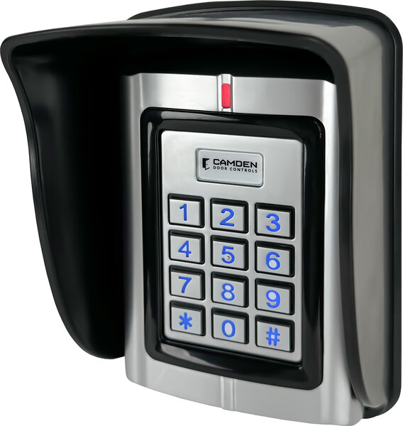
Stand-alone prox reader & keypad, 1 relay, 20000 users Variant record generated from manufacturer nomenclature (https://www.camdencontrols.com/products/CV_550_SPK); price inherited from product #3632 pending owner confirmation.
Stand-alone prox reader & keypad, 1 relay, 20000 users Variant record generated from manufacturer nomenclature (https://www.camdencontrols.com/products/CV_550_SPK); price inherited from product #3632 pending owner confirmation.
| Low-voltage wiring | Connection count needs review |
|---|---|
| Preparation | Make the wiring arrangements before mounting the CV-550SPK V3 keypad. Select the documented wall or single-gang mounting arrangement and any rain/privacy shield; use the original fixing diagram and supplied mounting hardware for the actual support. Remove the mating screw as instructed, prepare the fixing positions, fit the keypad and shield and refit the mating screw. Confirm cable-entry and rear clearance before drilling; the product face dimensions and external reader read range are not cutout dimensions. |
| Electrical | The V3 installation instructions allow10-28 V AC or DC input. For DC, red is positive and black is ground; for AC, red is AC1 and light green is AC2, with the unused DC/AC lead treated as the matching diagram instructs. Do not confuse light green AC2 with the dark green Data0 lead. Lock relay contacts are separately rated1 A at30 VDC. Select the actual DC/AC input arrangement and lock, exit, position, alarm and Wiegand-reader/controller functions before specifying field conductors or cable runs. External-reader voltage limits must be checked independently of the keypad input range. |
| Preparation required | Yes |
| Electrical wiring required | Yes |
| Conditional connections | DC power supply to keypad: cable runs quantity unspecified; conductor count unspecified; wire type not documented; size unspecified; shielding unspecified; rating unspecified; endpoints Red wire (+ve) to Black wire (GND) to 10-28 V DC power supply; when Installation configuration is Base product, DC power configuration only: red to positive and black to ground; the light green wire is not used. The conductor count is the two powered wires in this configuration, not a cable-run count.; AC power supply to keypad: cable runs quantity unspecified; conductor count unspecified; wire type not documented; size unspecified; shielding unspecified; rating unspecified; endpoints Red wire (AC1) to Light green wire (AC2) to 10-28 V AC power supply; when Installation configuration is Base product, alternative AC power configuration only: red (AC1) to one AC wire and light green (AC2) to the other; the black wire is not used. Do not confuse the light green wire with the dark green Data 0 wire.; Relay output to door strike or maglock: cable runs quantity unspecified; conductor count unspecified; wire type not documented; size unspecified; shielding unspecified; rating unspecified; endpoints Blue NO to Purple COM to Orange NC to Door strike or maglock; when Installation configuration is Base product, control circuit, only when a strike or maglock is connected. Use COM with NO or NC as the lock type requires; this is separate from the keypad power supply.; Exit button and door position switch inputs: cable runs quantity unspecified; conductor count unspecified; wire type not documented; size unspecified; shielding unspecified; rating unspecified; endpoints Yellow OPEN to Brown D_IN to Black GND to Push-to-exit switch to Door position switch; when Installation configuration is Optional accessory selected: IF a push-to-exit switch and/or door position switch is selected for the installation.; Alarm/doorbell output to annunciator: cable runs quantity unspecified; conductor count unspecified; wire type not documented; size unspecified; shielding unspecified; rating unspecified; endpoints Grey ALARM to Alarm annunciator CM-AF142SO; when Installation configuration is Optional accessory selected: IF an alarm annunciator or doorbell device is selected.; Wiegand output to access controller: cable runs quantity unspecified; conductor count unspecified; wire type not documented; size unspecified; shielding unspecified; rating unspecified; endpoints Green D0 to White D1 to Black GND to Access controller reader terminals; when Installation configuration is Optional accessory selected: IF the keypad is used in reader mode as a Wiegand reader to an access controller.; External Wiegand card reader input: cable runs quantity unspecified; conductor count unspecified; wire type not documented; size unspecified; shielding unspecified; rating unspecified; endpoints Green D0 to White D1 to External reader CV-7400; when Installation configuration is Optional accessory selected: IF an external Wiegand card reader is selected; the keypad must be configured for single door mode. |

Reviews
There are no reviews yet.