
Description
Series: CM-SR Series
Type: Receiver and Transmitters
Configuration: Receiver
2 channel 868 Mhz. wireless relay receiver
Brand: Camden
Manufacturer Part Number: CM-SRX2
Source: Camden Controls product page
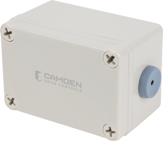
2 channel 868 Mhz. wireless relay receiver
Series: CM-SR Series
Type: Receiver and Transmitters
Configuration: Receiver
2 channel 868 Mhz. wireless relay receiver
Brand: Camden
Manufacturer Part Number: CM-SRX2
Source: Camden Controls product page
The CM-SR Series is a high-security 868.35MHz wireless system consisting of the CM-SRX2 stand-alone relay receiver (rolling code, 19 trillion combinations, 2-channel, 30 transmitter capacity, IP65 rated, built-in antenna) and the CV-WTX2 ultra-compact two-button fob transmitter. It is designed to activate locking devices such as electric strikes and automatic gate/door operators for one- or two-door access control.
| Voltage | 12V or 24V AC/DC (CM-SRX2 receiver) |
|---|---|
| Frequency | 868.35 MHz |
| Current draw | CM-SRX2: 80mA max; CV-WTX2 fob: 12mA |
| Relay | (1) SPST normally open, 1st relay momentary, 2nd momentary or latching/bi-stable, SPST normally closed, 1A @ 30 VDC |
| Temperature | CM-SRX2: -4°F to 185°F (-20°C to +85°C); CV-WTX2: -4°F to 131°F (-20°C to +55°C) |
| Dimensions | CM-SRX2: 2-17/32"W x 3-3/4"H x 2-7/32"D (64mm x 95mm x 56mm); CV-WTX2: 1-15/32"W x 2-5/32"H x 3/8"D (37mm x 55mm x 10mm) |
| Low-voltage wiring | Required |
| Basis | Structured, independently qualified product connection evidence |
| Preparation | Attach the rear housing to the wall using the supplied plugs and screws. Route cables through the receiver opening with the supplied grommet, then seal and fasten the front cover to the base. Match the voltage jumper to the supply before energizing. Select transmitter channel/relay assignments and relay-two impulse or bi-stable behavior, then verify the connected lock operation. Use the actual housing as the mounting reference. |
| Electrical | The receiver has a separate power input for 12V or 24V AC/DC. In the illustrated board, the voltage jumper is ON for 12V and OFF for 24V; for DC the left power terminal is positive. R1 is the normally-open output shown with a door strike; R2 is the normally-closed output shown with a maglock. Each selected low-voltage relay circuit uses the corresponding pair of R1 or R2 terminals, separate from the two-conductor receiver supply. The controlled locks have separate supplies in the diagram: contact-loop conductor counts do not count the whole lock-power circuit or its cable runs. Only relay two can change between impulse and bi-stable using the mode jumper; changing relay one mode requires the manufacturer. Antenna GND/ANT is separate from these circuits; confirm whether the delivered antenna is internal or an external accessory before specifying antenna cable. |
| Preparation required | Yes |
| Electrical wiring required | Yes |
| Conditional connections | Antenna connection: cable runs quantity unspecified; conductor count unspecified; wire type not documented; size unspecified; shielding unspecified; rating unspecified; endpoints CM-SRX2 GND/ANT terminal to Antenna; when Installation configuration is The diagram labels an antenna connection (item 1) at the GND/ANT terminal. Whether the antenna is a factory lead or a field cable is not documented.; CM-SRX2 power input: cable runs quantity unspecified; 2 conductor(s); wire type not documented; size unspecified; shielding unspecified; rating Field cable specification and physical route/run quantities require installation selection.; endpoints External matched AC/DC supply to 12/24V power terminal pair; when Installation configuration is Match voltage jumper; left positive for DC.; CM-SRX2 relay 1 NO contact loop: cable runs quantity unspecified; 2 conductor(s); wire type not documented; size unspecified; shielding unspecified; rating Field cable specification and physical route/run quantities require installation selection.; endpoints R1 terminal pair to External low-voltage door-strike circuit; when Installation configuration is Shown NO strike circuit; full lock-power circuit separately designed.; CM-SRX2 relay 2 NC contact loop: cable runs quantity unspecified; 2 conductor(s); wire type not documented; size unspecified; shielding unspecified; rating Field cable specification and physical route/run quantities require installation selection.; endpoints R2 terminal pair to External low-voltage maglock circuit; when Installation configuration is Shown NC maglock circuit; select impulse/bi-stable mode and separate lock supply. |


Reviews
There are no reviews yet.