
Description
Series: Lazerpoint™
Type: 915Mhz. Wireless Door Control System
Configuration: Receivers
Basic Single Relay Receiver
Brand: Camden
Manufacturer Part Number: CM-RX-91
Source: Camden Controls product page
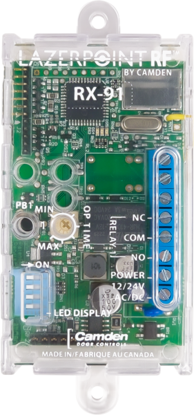
Basic Single Relay Receiver
Series: Lazerpoint™
Type: 915Mhz. Wireless Door Control System
Configuration: Receivers
Basic Single Relay Receiver
Brand: Camden
Manufacturer Part Number: CM-RX-91
Source: Camden Controls product page
Lazerpoint RF is a battery-powered 915MHz wireless door control system offering spread-spectrum wireless communication, signal-strength indicators, and 'push and learn' transmitter registration for easy installation. It spans the widest range of transmitters, receivers, activation devices, and switch boxes, including the CM-RX-90 single-relay receiver with 3 operating modes and the RX-92 two-channel receiver with 6 operating modes.
| Wireless frequency | 915 MHz spread spectrum |
|---|---|
| Battery | multi-year battery life (AAA alkaline or lithium), with low-battery audible alerts, fuel-gauge indicator, and stuck-switch indicator |
| CM-RX-90 receiver | 1 relay, 3 operating modes (delayed, non-delayed, latched) |
| RX-92 receiver | 2 channels, 6 operating modes |
| Fob options | 1, 2, and 4-button ADA-compliant key fobs |
| Low-voltage wiring | Required |
| Basis | Structured, independently qualified product connection evidence |
| Preparation | The RX-91 receiver is designed to mount inside the automatic door header, using the screw holes at each end of the case or the supplied Velcro. Mounting is 2 #8 screws at 4 inch centres, or Velcro. Power readiness at 12/24 V AC/DC is also needed (see wiring). Other site-dependent preparation, such as header space, is not documented. |
| Electrical | Connect the external supply to terminals 1 and 2; the manual specifies 12 or 24 Volt AC or DC and non-polarized terminals. Relay 1 uses terminal 3 NO, 4 COM and 5 NC. The illustrated low-voltage door-operator interface uses NO/COM; select NC instead only for the required control logic. Power and the selected relay loop each need two external field conductors, while physical cable grouping and routes remain site choices. Enrol the transmitter through PB1, set the hold delay and walk-test signal strength and operation. Optional RF daughterboards are local plug-in accessories, and the temporary CM-RFCT LED tool is removed after installation. Confirm actual receiver revision and accessory compatibility; the source dimensions and daughterboard descriptions differ between revisions. Safety devices must be wired directly to the operator control box as instructed by the manufacturer. |
| Preparation required | Yes |
| Electrical wiring required | Yes |
| Conditional connections | Optional plug-in daughterboard for other RF frequencies: cable runs quantity unspecified; conductor count unspecified; wire type not documented; size unspecified; shielding unspecified; rating unspecified; endpoints RX-91 receiver to RX-DBB / RX-DBO / RX-DBR / RX-DBW daughterboard; when Installation configuration is Optional accessory selected: IF a daughterboard accessory is selected; it can be factory or field installed. Installation details are on drawing DRG-RX-DB (page 6), which was not visually supplied.; Optional CM-RFCT cable tool for viewing LEDs: cable runs quantity unspecified; conductor count unspecified; wire type not documented; size unspecified; shielding unspecified; rating unspecified; endpoints RX-91 side opening to CM-RFCT cable tool; when Installation configuration is Optional accessory selected: IF the CM-RFCT cable tool accessory is selected; it is a plug-in tool that is unplugged after installation.; CM-RX-91 power input: cable runs quantity unspecified; 2 conductor(s); wire type not documented; size unspecified; shielding unspecified; rating Field cable specification and physical route/run quantities require installation selection.; endpoints External matched AC/DC supply to Terminals 1 and 2; when Installation configuration is Base power; non-polarized.; CM-RX-91 selected NO output: cable runs quantity unspecified; 2 conductor(s); wire type not documented; size unspecified; shielding unspecified; rating Field cable specification and physical route/run quantities require installation selection.; endpoints Terminal 3 NO and 4 COM to External low-voltage operator input; when Installation configuration is Illustrated NO interface; NC alternative depends on controlled device. |


Reviews
There are no reviews yet.