
Description
Series: Kinetic by Camden™
Type: 900Mhz. No-Battery Wireless Door Control System
V2 Kinetic/Lazerpoint Advanced 1 Relay Receiver
Brand: Camden
Manufacturer Part Number: CM-RX-90
Source: Camden Controls product page
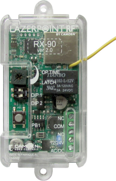
V2 Kinetic/Lazerpoint Advanced 1 Relay Receiver
Series: Kinetic by Camden™
Type: 900Mhz. No-Battery Wireless Door Control System
V2 Kinetic/Lazerpoint Advanced 1 Relay Receiver
Brand: Camden
Manufacturer Part Number: CM-RX-90
Source: Camden Controls product page
Kinetic by Camden is a 900 MHz no-battery wireless door control system that uses the energy generated by pressing the switch to power the wireless transmitter, eliminating batteries and their disposal. It pairs battery-less push plate switches with the compact CM-RX-90 wireless receiver (field-selectable momentary, delayed, or latching relay operation) and is compatible with all brands of automatic door operators for indoor or outdoor use.
| Frequency | 900 MHz Fixed Frequency |
|---|---|
| Range open air | Up to 300 ft |
| Range in operator header | Up to 70 ft |
| Temperature | -40°F to 185°F (-40°C to 85°C) switch; Alkaline receiver battery 32°F to 122°F (0°C to 50°C), Lithium -40°F to 122°F (-40°C to 50°C) |
| Input voltage | 12/24V, AC/DC (CM-RX-90 receiver) |
| Output | CM-RX-90: (1) SPDT relay, 3 modes |
| Current draw | CM-RX-90: 23mA – 43mA |
| Time delay | CM-RX-90: 1-30 seconds |
| Dimensions | CM-RX-90 receiver: 3-1/2"H x 1-1/2"W x 13/16"D (89mm x 38mm x 21mm) |
| Low-voltage wiring | Required |
| Basis | Structured, independently qualified product connection evidence |
| Preparation | This listing identifies the V2 receiver. Mount it inside the automatic-door header using its end screw holes or supplied Velcro; the receiver specification calls for two #4 screws at 3-inch centers when screw-mounted. Check the actual receiver footprint and mechanical drawing rather than the separate pushbutton-box depth. Set DIP2 for Kinetic or Lazerpoint transmitters, select delayed/no-delay/latching operation, learn the actual transmitters and set timing. After adjusting RF range, set the relay timing again as directed by the manual. |
| Electrical | For the V2 receiver in this listing, connect 12/24VAC/DC to terminals1 and2, the two red power leads; these inputs are not polarity sensitive and use two circuit conductors. Output NO is terminal3 blue, common4 grey and NC5 orange. Common with one selected throw uses two external low-voltage conductors; common with both throws uses three. Select actual delay/no-delay/latching behavior and controller circuit. At 24VAC the receiver specification gives 23mA nominal and 43mA maximum. Contact ratings are separate from operating power. The manufacturer directs safety devices to be wired directly to the operator control box, the RF system must not serve as a safety device. Determine field cable type, gauge, shielding and physical routes separately from the receiver factory leads. |
| Preparation required | Yes |
| Electrical wiring required | Yes |
| Conditional connections | CM-RX-90 V2 operating power terminals1/2: cable runs quantity unspecified; 2 conductor(s); wire type not documented; size unspecified; shielding unspecified; rating Field cable type, gauge, shielding and physical route unspecified; factory leads are distinct.; endpoints Compatible12/24VAC/DC supply to V2 receiver power1/2, red/red; when Installation configuration is Exact V2 receiver in this listing; power terminals are not polarity sensitive.; Selected CM-RX-90 V2 common with NO: cable runs quantity unspecified; 2 conductor(s); wire type not documented; size unspecified; shielding unspecified; rating Field cable type, gauge, shielding and physical route unspecified; factory leads are distinct.; endpoints Selected low-voltage controlled circuit to V2 receiver 4 grey COM and3 blue NO; when Installation configuration is When this NO output is selected for the actual operating mode; alternatives are not additive.; Selected CM-RX-90 V2 common with NC: cable runs quantity unspecified; 2 conductor(s); wire type not documented; size unspecified; shielding unspecified; rating Field cable type, gauge, shielding and physical route unspecified; factory leads are distinct.; endpoints Selected low-voltage controlled circuit to V2 receiver 4 grey COM and5 orange NC; when Installation configuration is When this NC output is selected for the actual operating mode; alternatives are not additive.; Selected CM-RX-90 V2 common with NO and NC: cable runs quantity unspecified; 3 conductor(s); wire type not documented; size unspecified; shielding unspecified; rating Field cable type, gauge, shielding and physical route unspecified; factory leads are distinct.; endpoints Selected low-voltage controlled circuit to V2 receiver 4 grey COM,3 blue NO and5 orange NC; when Installation configuration is When this NO and NC output is selected for the actual operating mode; alternatives are not additive. |


Reviews
There are no reviews yet.