
Description
Series: CM-9800
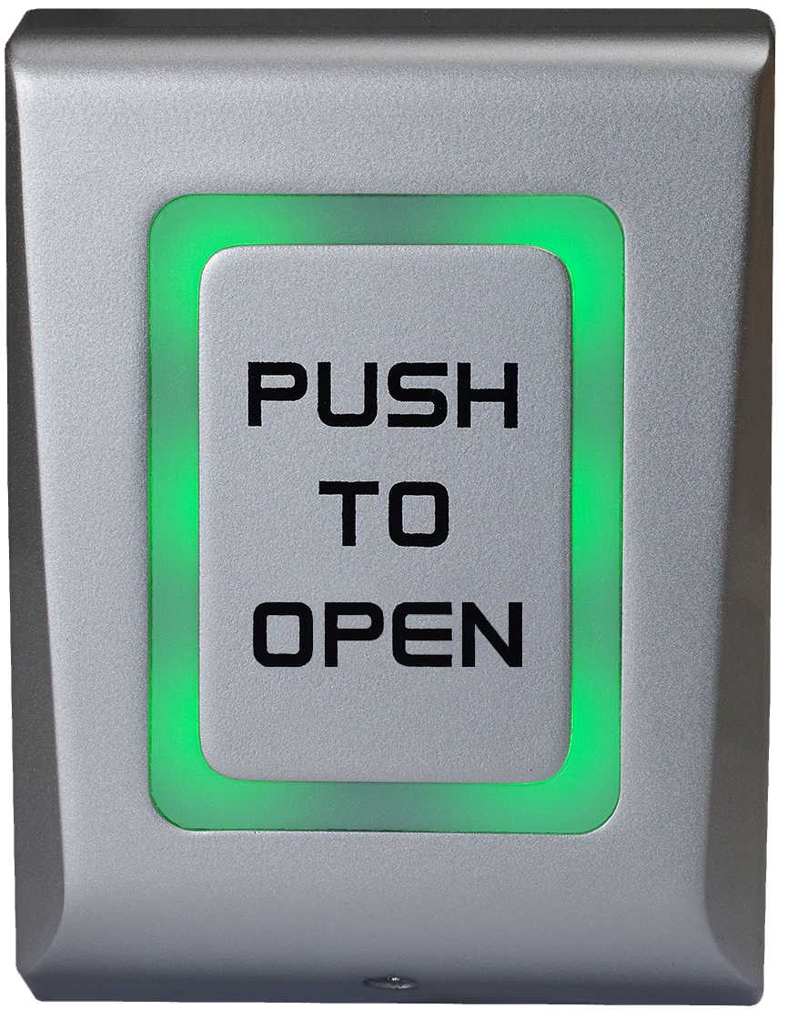
Type: Illuminated Capacitive Push/Exit Switch
Brand: Camden
Manufacturer Part Number: CM-9800/3
Source: Camden Controls product page
Series: CM-9800 Type: Illuminated Capacitive Push/Exit Switch Brand: Camden Manufacturer Part Number: CM-9800/3 Source: Camden Controls product page
Series: CM-9800
Type: Illuminated Capacitive Push/Exit Switch
Brand: Camden
Manufacturer Part Number: CM-9800/3
Source: Camden Controls product page
Camden Door Controls CM-9800 Series surface mount capacitive touch switches, with LED illumination, are vandal and weather resistant with an IP66 rating and a cast metal design, featuring an adjustable 0-60 second relay timer. The CM-9800 has an external input so the switch illumination can be activated by either the switch status or the door lock status.
| Input voltage | 12V to 24V AC/DC |
|---|---|
| Current draw | Max. 65mA |
| Relay output | 2A @ 24 VDC or 120 VAC |
| Set relay time | 0.5 to 60 seconds or toggle (ON/OFF) |
| Temperature | -4°F to 122°F (-20°C to 50°C) |
| Material | Die-Cast Aluminum Alloy housing |
| Protection | IP66 |
| Dimensions | 3-3/8" W x 4-9/16" H x 13/16" D (86mm x 116mm x 21mm) |
| Contact rating | 2 Amp, Form 'C' |
| Low-voltage wiring | Connection count needs review |
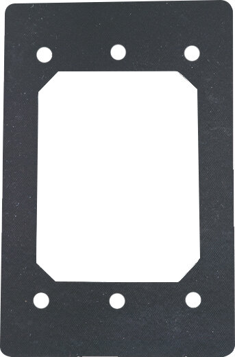
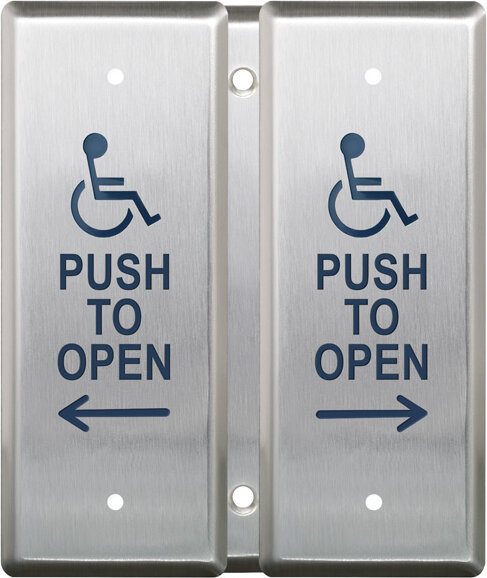
| Preparation | Use the supplied drilling template on the selected wall or flat surface. Drill the three marked holes, insert the supplied 6mm wall plugs, route cables through the backplate openings and fasten the backplate with the three 4 x 30mm screws. After wiring, place the housing over the backplate, engage its tab, slide down and secure the bottom with the M3 x 6mm security screw. Preserve the PUSH TO OPEN graphic. The manual requires correct earth grounding for transient protection but does not identify the earth connection point in its lead table; confirm that connection and do not assume LED common is protective earth. |
| Electrical | Use 12-24V AC/DC on red and black, two external supply conductors; maximum documented consumption is 65mA. The controller REX example uses purple NO and white COM, two conductors. For other relay-interface selections, white COM and pink NC use two, or COM plus both NO and NC use three; select the needed configuration rather than adding alternatives. If tamper supervision is connected, grey and blue form its separate two-conductor interface. External LED control uses orange LR-, yellow LG- and green LED common, three conductors to the controller when selected. Keep LED common distinct from protective earth. Two direct-load examples have NO/NC headings inconsistent with the drawn terminals; verify the actual load circuit before using those examples. Select timer/toggle, buzzer, backlight and LED settings for the installation. Factory leads do not establish physical cable-run counts. Field cable type, gauge, shielding and run quantities remain unspecified. |
| Preparation required | Yes |
| Electrical wiring required | Yes |
| Conditional connections | Selected CM-9800/3 Power input: cable runs quantity unspecified; 2 conductor(s); wire type not documented; size unspecified; shielding unspecified; rating Field cable type, gauge, shielding and physical run quantity unspecified. Interfaces and factory tails are distinct from cable jackets.; endpoints CM-9800/3 red and black to Selected external low-voltage supply; when Installation configuration is Base power supply interface. No physical cable-run count inferred.; Selected CM-9800/3 NO relay circuit: cable runs quantity unspecified; 2 conductor(s); wire type not documented; size unspecified; shielding unspecified; rating Field cable type, gauge, shielding and physical run quantity unspecified. Interfaces and factory tails are distinct from cable jackets.; endpoints CM-9800/3 purple NO and white COM to Selected external low-voltage controller or verified controlled circuit; when Installation configuration is Selected controller REX or other verified NO interface; alternative to NC or both-throw configuration. No physical cable-run count inferred.; Selected CM-9800/3 NC relay circuit: cable runs quantity unspecified; 2 conductor(s); wire type not documented; size unspecified; shielding unspecified; rating Field cable type, gauge, shielding and physical run quantity unspecified. Interfaces and factory tails are distinct from cable jackets.; endpoints CM-9800/3 pink NC and white COM to Selected external low-voltage controller or verified controlled circuit; when Installation configuration is Selected NC interface; alternative to NO or both-throw configuration. Verify actual direct-load circuit because example headings conflict. No physical cable-run count inferred.; Selected CM-9800/3 Both relay throws: cable runs quantity unspecified; 3 conductor(s); wire type not documented; size unspecified; shielding unspecified; rating Field cable type, gauge, shielding and physical run quantity unspecified. Interfaces and factory tails are distinct from cable jackets.; endpoints CM-9800/3 purple NO, pink NC and white COM to Selected external low-voltage controller or verified controlled circuit; when Installation configuration is Selected use of both throws with common; alternative to using only NO or NC. No physical cable-run count inferred.; Selected CM-9800/3 Tamper supervision: cable runs quantity unspecified; 2 conductor(s); wire type not documented; size unspecified; shielding unspecified; rating Field cable type, gauge, shielding and physical run quantity unspecified. Interfaces and factory tails are distinct from cable jackets.; endpoints CM-9800/3 grey and blue tamper pair to Selected external low-voltage controller or verified controlled circuit; when Installation configuration is Only when external tamper supervision is connected. No physical cable-run count inferred.; Selected CM-9800/3 External LED control: cable runs quantity unspecified; 3 conductor(s); wire type not documented; size unspecified; shielding unspecified; rating Field cable type, gauge, shielding and physical run quantity unspecified. Interfaces and factory tails are distinct from cable jackets.; endpoints CM-9800/3 orange LR-, yellow LG- and green LED common to Selected external low-voltage controller or verified controlled circuit; when Installation configuration is Only when external controller LED control is selected; configure the corresponding DIP settings. No physical cable-run count inferred. |
Reviews
There are no reviews yet.