
Description
Series: CM-9600/9610
Type: Illuminated Piezoelectric Push/Exit Switch
Configuration: Narrow Faceplate
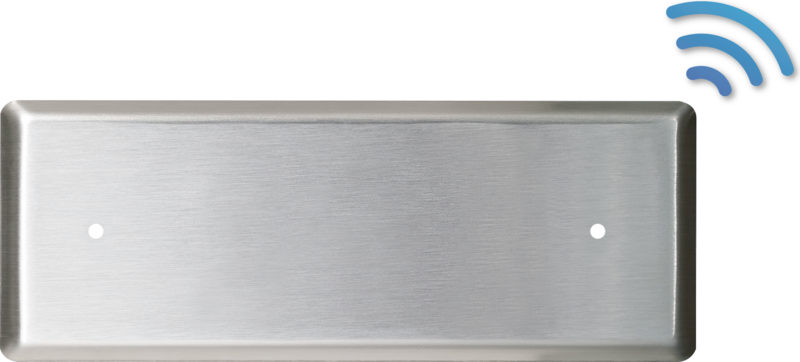
Illuminated piezoelectric push button, blank
Brand: Camden
Manufacturer Part Number: CM-9610
Source: Camden Controls product page
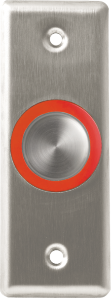
Illuminated piezoelectric push button, blank
Series: CM-9600/9610
Type: Illuminated Piezoelectric Push/Exit Switch
Configuration: Narrow Faceplate
Illuminated piezoelectric push button, blank
Brand: Camden
Manufacturer Part Number: CM-9610
Source: Camden Controls product page
(114mm) CM-9600/7 Camden Door Controls, CM-9600 and CM-9610 Series flush mount illuminated piezo push switches offer high visibility and weather/vandal resistance. The units feature a 1 ¾” heavy duty stainless steel faceplate and adjustable 40 second timer. The CM-9600 is single gang (2 3/4”) width and the CM-9610 is only (1 3/4”) wide, (45mm) perfect for door frames or narrow areas.
| Low-voltage wiring | Connection count needs review |
|---|---|
| Preparation | Provide the narrow-jamb electrical-box mounting arrangement with clearance for the documented 1.5 inch deep unit. Fasten using the two supplied #6-32 machine screws. Select the timer delay and relay operating mode for the actual controlled device before commissioning; set the illumination jumpers for the desired red/green/off state. |
| Electrical | Supply 12-24 VDC to the red/black power pair, which powers both timer and LEDs; this is one two-conductor electrical interface, not a physical cable-run quantity. For the selected relay circuit, use NO1 with COM1 or COM2 with NC2, two external conductors for each used pair. If both pairs are used, keep their separately labelled commons distinct; the drawing does not establish a common bridge. The adjustable on-time is 1-40 seconds. In the documented fail-safe jumper position the relay is normally on and turns off when the button is pressed or power is lost. Set the relay mode and LED jumpers for the actual installation. Optional remote LED-control wiring remains separate. The manufacturer does not specify field cable type, gauge, shielding or physical run quantities. |
| Preparation required | Yes |
| Electrical wiring required | Yes |
| Conditional connections | Selected CM-9610 Power input: cable runs quantity unspecified; 2 conductor(s); wire type not documented; size unspecified; shielding unspecified; rating Field cable type, gauge, shielding and physical runs unspecified; no common bridge or cable-jacket count inferred.; endpoints Selected external 12-24VDC supply to CM-9610 positive and negative input; when Installation configuration is Base shared timer and LED supply. Physical run quantity remains unknown.; Selected CM-9610 NO contact circuit: cable runs quantity unspecified; 2 conductor(s); wire type not documented; size unspecified; shielding unspecified; rating Field cable type, gauge, shielding and physical runs unspecified; no common bridge or cable-jacket count inferred.; endpoints Selected external low-voltage controlled circuit to CM-9610 NO1 and COM1; when Installation configuration is Use this contact pair only for the selected function. Both pairs may be used separately; do not bridge COM1 and COM2 by assumption. Physical run quantity remains unknown.; Selected CM-9610 NC contact circuit: cable runs quantity unspecified; 2 conductor(s); wire type not documented; size unspecified; shielding unspecified; rating Field cable type, gauge, shielding and physical runs unspecified; no common bridge or cable-jacket count inferred.; endpoints Selected external low-voltage controlled circuit to CM-9610 COM2 and NC2; when Installation configuration is Use this contact pair only for the selected function. Both pairs may be used separately; do not bridge COM1 and COM2 by assumption. Physical run quantity remains unknown. |

Reviews
There are no reviews yet.