
Description
Series: CM-800 Series
Type: Rocker Switches
Configuration: Beige Plastic
Remote Door Release Switch SPDT Momentary or Maintained
Brand: Camden
Manufacturer Part Number: CM-850
Source: Camden Controls product page
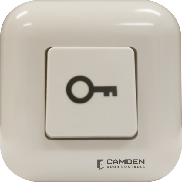
Remote Door Release Switch SPDT Momentary or Maintained
Series: CM-800 Series
Type: Rocker Switches
Configuration: Beige Plastic
Remote Door Release Switch SPDT Momentary or Maintained
Brand: Camden
Manufacturer Part Number: CM-850
Source: Camden Controls product page
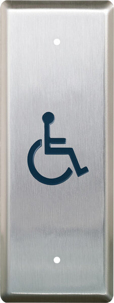
Camden's CM-800 Series rocker switches are surface-mount remote door release switches available in weather-resistant aluminum (CM-810/820) or low-profile plastic (CM-830/840/850), designed for releasing maglocks or door strikes and ideal for under-desk or wall mounting in reception areas. The CM-850 model provides Form 'C' contacts field-configurable for momentary (default) or maintained operation.
| Contact rating | CM-810/820/830/840: 20 Amps; CM-850: 10 Amps @ 12/24V DC |
|---|---|
| Configuration | CM-810/830: Momentary SPDT (Common, N.C., N.O.); CM-820/840: Maintained SPDT; CM-850: Momentary or Maintained SPDT |
| Switch life | 100,000 cycles |
| Finish | Beige (CM-850) |
| Dimensions | CM-810/820: 2-1/2"H x 2-1/4"W x 1-3/8"D (63mm x 57mm x 35mm); CM-830/840: 2-7/8"H x 1-1/2"W x 3/4"D (73mm x 38mm x 19mm); CM-850: 2-3/8"H x 2-3/8"W x 5/8"D (60mm x 60mm x 17mm) |
| Low-voltage wiring | Required |
| Basis | Structured, independently qualified product connection evidence |
| Preparation | Choose an accessible position under a desk/counter or on a wall, away from accidental activation. Release the bezel gently with a small flat-head screwdriver at its mounting tab. For under-counter mounting, fasten the contact assembly with the supplied self-tapping screws without overtightening and allow room for the housing at the edge. For wall mounting, level the assembly, mark both mounting holes, drill or punch the marked spots, fit the supplied anchors flush and secure the assembly. After wiring, press the housing on until it clicks. For maintained operation, follow the manual spring-removal procedure and retain the spring for restoring momentary operation. |
| Electrical | The switch contact is wired into the selected low-voltage circuit. For the documented fail-secure strike circuit, common connects to supply positive and NO to strike positive; strike negative returns directly to supply negative. For the maglock circuit, common connects to supply positive and NC to maglock positive; maglock negative returns directly to supply negative. Each of these selected switch loops uses two external conductors at the switch, separate from the lock supply return. For the maintained panic-alarm example, connect common to panel input and NC to panel ground with two conductors. These are alternative circuits; do not add all example counts together. The maglock heading says momentary while its caption says maintained; select and verify the required operating mode. Field cable type, gauge, shielding and physical runs remain unspecified. Contact rating is not a switch power-supply requirement. |
| Preparation required | Yes |
| Electrical wiring required | Yes |
| Conditional connections | Selected CM-850 Fail-secure strike switch interface: cable runs quantity unspecified; 2 conductor(s); wire type not documented; size unspecified; shielding unspecified; rating Field cable type, gauge, shielding and physical runs unspecified; this count describes only the selected switch interface.; endpoints Selected external Fail-secure strike circuit to CM-850 common and NO; when Installation configuration is Alternative installation: Fail-secure strike, momentary. Two external switch-interface conductors; lock negative return and cable-run quantity are separate.; Selected CM-850 Maglock switch interface: cable runs quantity unspecified; 2 conductor(s); wire type not documented; size unspecified; shielding unspecified; rating Field cable type, gauge, shielding and physical runs unspecified; this count describes only the selected switch interface.; endpoints Selected external Maglock circuit to CM-850 common and NC; when Installation configuration is Alternative installation: Maglock, verify selected mode; manual heading and caption conflict. Two external switch-interface conductors; lock negative return and cable-run quantity are separate.; Selected CM-850 Panic alarm switch interface: cable runs quantity unspecified; 2 conductor(s); wire type not documented; size unspecified; shielding unspecified; rating Field cable type, gauge, shielding and physical runs unspecified; this count describes only the selected switch interface.; endpoints Selected external Panic alarm circuit to CM-850 common and NC; when Installation configuration is Alternative installation: Panic alarm, maintained. Two external switch-interface conductors; lock negative return and cable-run quantity are separate. |

Reviews
There are no reviews yet.