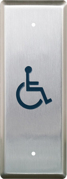
Camden CM-8436VR – 36″ x 4.5″ Column™ aluminum side load push plate switch with hands-free sensor, anodized clear finish

$50.00

36\” x 4.5\” Column™ aluminum side load push plate switch with hands-free sensor, anodized clear finish

SKU: CM-8436VR
Category:
Brands:

Description

Series: CM-74/75 & CM-84/85 Series

Type: Column™ Push Plate Switches

Configuration: 4.5" Wide

36" x 4.5" Column™ aluminum side load push plate switch with hands-free sensor, anodized clear finish

Brand: Camden

Manufacturer Part Number: CM-8436VR

Source: Camden Controls product page
Additional information

graphic

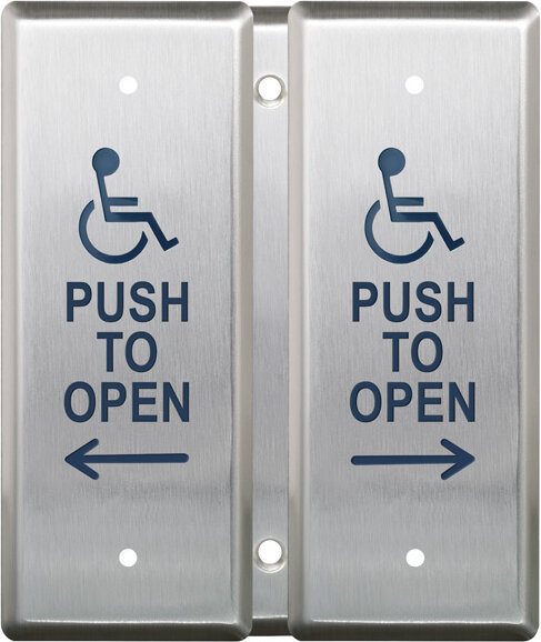
/1 no graphic, /2 wheelchair, /20 wheelchair+foot icon, /2AL wheelchair+arrow left, /2AR wheelchair+arrow right, /3 push to open, /4 wheelchair+push to open, /40 wheelchair+push to open, /4AL wheelchair+push to open, /4AR wheelchair+push to open, /80 lock (red)+foot icon, /8B lock+push to lock, /8C lock symbol, /A2 active wheelchair, /A20 active wheelchair+foot i, /A4 active wheelchair+push t, /A40 active wheelchair+push t

Reviews

There are no reviews yet.

Be the first to review “Camden CM-8436VR – 36″ x 4.5″ Column™ aluminum side load push plate switch with hands-free sensor, anodized clear finish”

Your email address will not be published. Required fields are marked *

Camden's CM-74 and CM-75 Series top-activation Column push plate switches are surface mounted and designed for installations with no obstruction above the unit, offering a discreet appearance. The CM-84 and CM-85 Series side-activation Column switches are two-piece units with a surface-mounted back box, designed for use when an overhead obstruction prevents a top-activation model, when mounting on a narrow curtain wall, or when the unit must pass through a glass panel.

Product specifications
Contact rating standard models 15 A @ 30VDC
Contact rating vr models 1 A @ 30VDC
Voltage vr models 12 to 24 VDC +/- 10%
Contact type standard momentary contact switch, single pole double throw, Form C
Contact type vr common/normally open/normally closed
Depth (CM-84/85) 2-1/4" (32mm)
Width (CM-74) 4-1/2"
Width (CM-75) 6"
Width (CM-84) 4-1/2"
Width (CM-85) 6"
Low-voltage wiring Required
BasisStructured, independently qualified product connection evidence
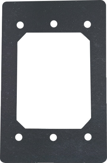
PreparationSelect the wall or frame location using the actual back-box template. Remove the end cap and separate the switch from its back box; mark mounting holes using the guide channels. Prepare the hardwiring entry at the selected height, secure the back box with the specified substrate anchors or tapped-frame screws, route the wiring through the entry and connect it before reassembly. Keep wiring clear of moving parts, slide the switch into the mounted back box, refit the cap and test both touchless and mechanical activation.
ElectricalUse12 to24VDC within the manufacturer10% tolerance; AC input is prohibited. Use suitable filtered regulated DC power and measure it before connection. Red is positive supply and black is0V. Green is relay NO, blue common and purple NC. In the direct door-operator example, power uses two external conductors and the NO/common control circuit uses two separate external conductors; the mechanical NO switch is parallel with that output. These circuit counts do not specify cable jackets or run quantities. Isolate unused leads individually. In default internal LED mode leave the mode pins open. Optional external LED mode requires the jumper: yellow controls green and white controls red, each pulled low to ground. Decide the external return routing separately. The1A at30VDC relay rating is a contact limit, not supply current.
Preparation requiredYes
Electrical wiring requiredYes
Conditional connectionsCM-8436VR DC power from separate regulated supply: cable runs quantity unspecified; 2 conductor(s); wire type not documented; size unspecified; shielding unspecified; rating Field cable type, gauge, shielding and physical run quantity unspecified.; endpoints External12-24VDC regulated supply to Red positive and black0V sensor leads; when Installation configuration is Separate DC power circuit in documented direct door-operator configuration; supply is not included.; CM-8436VR direct operator normally-open activation: cable runs quantity unspecified; 2 conductor(s); wire type not documented; size unspecified; shielding unspecified; rating Field cable type, gauge, shielding and physical run quantity unspecified.; endpoints Green NO and blue common with mechanical NO switch in parallel to External compatible low-voltage door-operator input; when Installation configuration is Documented direct door-operator NO activation configuration with sensor-controlled LEDs; purple NC unused, yellow/white LED leads unused.

Official manufacturer documents