
Description
Series: CM-700 Series
Type: 'Universal' Blue Pull Stations
Configuration:
Brand: Camden
Manufacturer Part Number: CM-702U
Source: Camden Controls product page
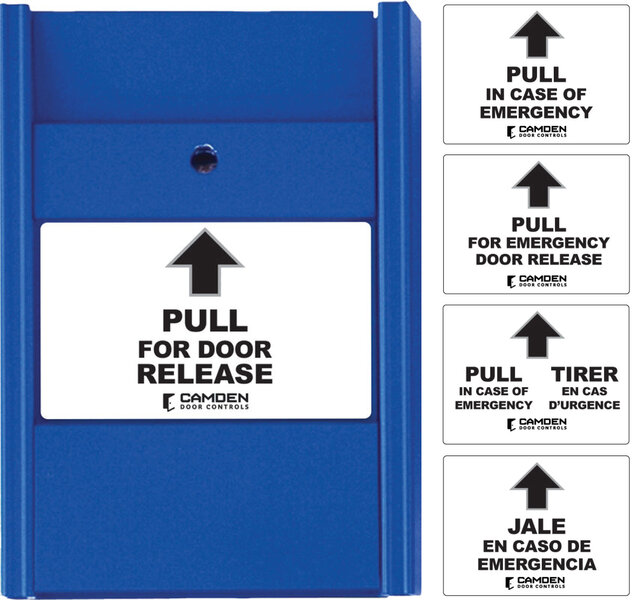
Series: CM-700 Series Type: 'Universal' Blue Pull Stations Configuration: Brand: Camden Manufacturer Part Number: CM-702U Source: Camden Controls product page
Series: CM-700 Series
Type: 'Universal' Blue Pull Stations
Configuration:
Brand: Camden
Manufacturer Part Number: CM-702U
Source: Camden Controls product page
CM-700 Series 'Universal' Blue Pull Stations are single-gang, vandal-resistant emergency pull stations for door release and emergency exit applications (not rated for fire alarm use), protruding only 3/4" from the wall and easily reset with a small screwdriver. Models are available with N/O, N/C, or both contacts, and an optional variant includes a built-in local alarm sounder.
| Contact rating | 1A @ 30 VDC |
|---|---|
| Construction | Extruded Aluminum |
| Mounting | Single gang electrical box |
| Dimensions | 4-1/2" W x 3-1/4" H x 1-3/8" D (114mm x 82mm x 35mm) |
| Sounder | 85dB @ 4" (10cm); 40mA @ 12 VDC |
| Low-voltage wiring | Connection count needs review |
| Preparation | Provide a single-gang electrical-box mounting arrangement and select the included label appropriate to this station. Verify the actual enclosure footprint and clearance before preparing the mounting surface: the product page and specification sheet give different dimensions. The station is reset using a small screwdriver; use the instructions for the delivered revision. This product is not rated for fire-alarm applications. |
| Electrical | The base universal station has two normally closed contacts. Contact states are specified with the pull station closed/reset; releasing it reverses the contact states. Wire the selected low-voltage controlled circuit to the actual station terminals. Contact quantity is not a field-conductor or physical cable-run count. The manufacturer contact rating does not establish a separate station supply requirement. The linked legacy wiring diagram omits the U suffix and depicts a keyed two-stage CM-703 arrangement; exact universal-variant terminal mapping has not been established. Obtain the exact installation diagram, connected-device requirements and site routing to determine field conductor count, cable runs, cable type, gauge and shielding. |
| Preparation required | Yes |
| Electrical wiring required | Yes |
| Conditional connections | Switch contact connection to the controlled circuit, through the wiring terminal (2 N/C switches): cable runs quantity unspecified; conductor count unspecified; wire type not documented; size unspecified; shielding unspecified; rating unspecified; endpoints CM-702U wiring terminal to external controlled circuit; when Installation configuration is Base product. The switch contacts are 2 x N/C when the station is closed/reset and change state when released. The cable boundary, number of runs and conductor count are not documented. |

Reviews
There are no reviews yet.