
Description
Series: CM-3000/3100 Series
Type: Illuminated Mushroom Pushbutton
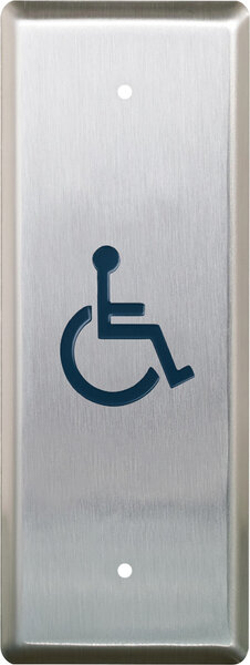
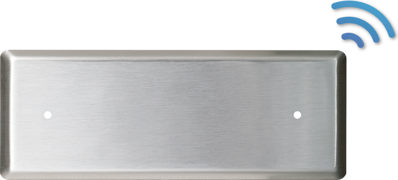
Configuration: Narrow Faceplate
Push/Pull Button, N/O & N/C, Maintained, 12V
Brand: Camden
Manufacturer Part Number: CM-3150
Source: Camden Controls product page
Push/Pull Button, N/O & N/C, Maintained, 12V
Series: CM-3000/3100 Series
Type: Illuminated Mushroom Pushbutton
Configuration: Narrow Faceplate
Push/Pull Button, N/O & N/C, Maintained, 12V
Brand: Camden
Manufacturer Part Number: CM-3150
Source: Camden Controls product page
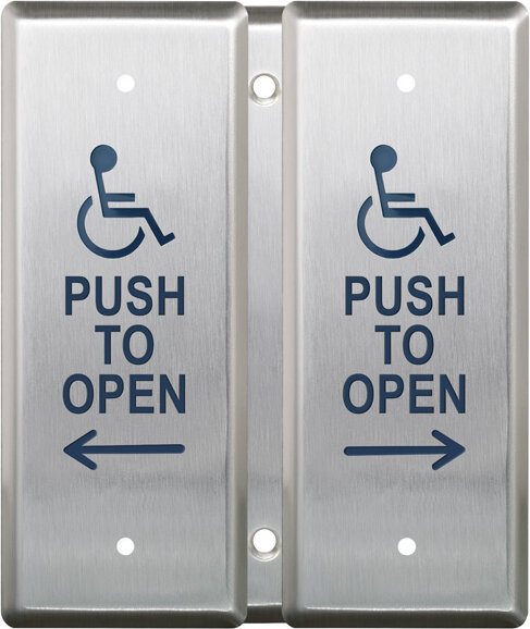
Camden Door Controls CM-3000/3100 Series Exit Switches are heavy duty push-buttons designed for industrial and commercial applications where illumination is required. Buttons are 1 5/8" (40mm) in diameter, available in red or green, with a 1/4" thick brushed aluminum faceplate in 1 3/4" or 2 3/4" widths. The switches are UL/CSA approved, rated 10 amps @ 30V DC, for either momentary or maintained operation.
| Low-voltage wiring | Required |
|---|---|
| Basis | Structured, independently qualified product connection evidence |
| Preparation | Provide the narrow door-jamb mounting arrangement for this model. Align and secure the brushed aluminum faceplate with the supplied mounting hardware, leaving room behind it for the contact block, LED and wiring. Verify clearance against the delivered assembly: the dimension table and side drawing give different depth figures. Select the actual surface or flush mounting arrangement before installation. |
| Electrical | CM-3150 uses a N/O and N/C DPST contact block with maintained push/pull action. For a selected direct 12/24 VDC control circuit, keep the N/O and N/C contact pairs distinct; the selected use and field conductor count are not established by the shared SPST diagrams. The LED supply is separate: connect two supply conductors at X1/X2 directly for 12 VDC; for 24 VDC put the supplied resistor in series with either X1 or X2. These interface counts do not state how many cable jackets/runs to pull. Field wire type and gauge are not specified by this manual; factory lead sizes are not field cable requirements. |
| Electrical wiring required | Yes |
| Conditional connections | Scoped installation connections for CM-3150: cable runs quantity unspecified; conductor count unspecified; wire type not documented; size unspecified; shielding unspecified; rating Selected installation configuration only; no universal field cable or cable-run count.; endpoints CM-3150 contact block and LED terminals where fitted to Selected external controlled circuit and separate LED supply where fitted; when Installation configuration is Use the N/O and N/C DPST contact configuration with push/pull maintained action for the controlled circuit. The N/O and N/C circuits use their corresponding contact pairs; do not reinterpret this DPST model as a shared-common changeover contact. LED power connects separately at X1/X2: direct for 12 VDC, or with the supplied series resistor in one lead for 24 VDC. Select switching and illumination circuits for the actual controller/application; terminal contacts and supplied tails do not establish a universal field cable count.; Separate LED low-voltage supply at X1/X2: cable runs quantity unspecified; 2 conductor(s); wire type not documented; size unspecified; shielding unspecified; rating Field wire type, conductor size, shielding and physical run quantity are not specified by this manufacturer manual. Select for the actual low-voltage system and site.; endpoints External selected12/24VDC supply to LED terminals X1 and X2; when Installation configuration is Selected direct12VDC supply:connect X1/X2 directly. Selected24VDC supply:insert the supplied resistor in series with either X1 or X2. This is the external LED supply pair, separate from the switch loop; physical cable runs are unknown.; N/O and N/C DPST low-voltage controlled contact circuit: cable runs quantity unspecified; conductor count unspecified; wire type not documented; size unspecified; shielding unspecified; rating Field wire type, conductor size, shielding and physical run quantity are not specified by this manufacturer manual. Select for the actual low-voltage system and site.; endpoints CM-3150 N/O and N/C DPST contact block to Selected external12/24VDC controlled circuit; when Installation configuration is Selected12/24VDC control circuit with maintained push/pull operation. Use the corresponding N/O and N/C contact pairs required by the selected application; do not assume a shared-common changeover circuit. Shared SPST diagrams do not establish a universal DPST field count. Physical cable runs remain unknown. |
Reviews
There are no reviews yet.