
Description
Series: CM-221 & CM-222 Series
Type: ValueWave™ Touchless Switches
Configuration: Wave To Open
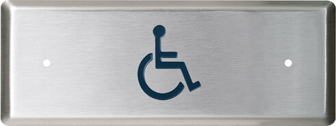
ValueWave™ Touchless Switch, Single Gang,
Brand: Camden
Manufacturer Part Number: CM-221/A42
Source: Camden Controls product page
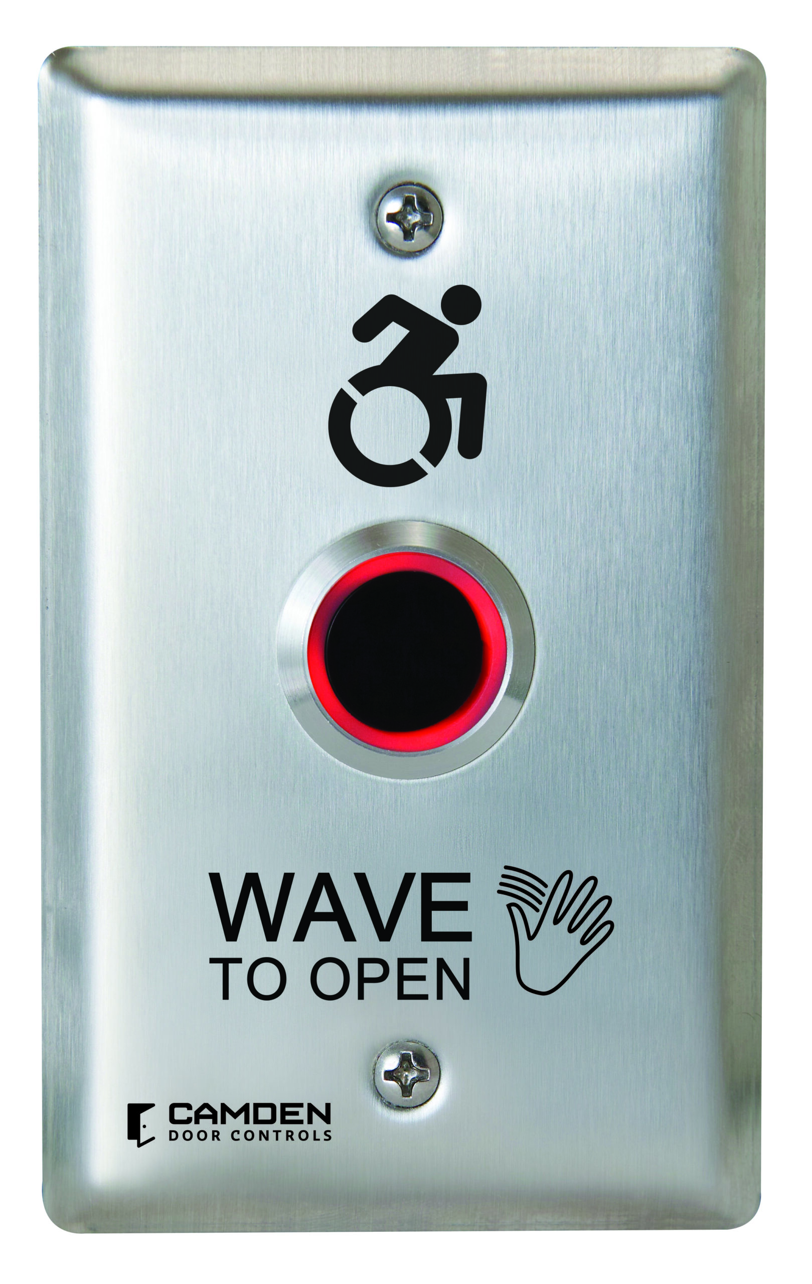
ValueWave™ Touchless Switch, Single Gang,
Series: CM-221 & CM-222 Series
Type: ValueWave™ Touchless Switches
Configuration: Wave To Open
ValueWave™ Touchless Switch, Single Gang,
Brand: Camden
Manufacturer Part Number: CM-221/A42
Source: Camden Controls product page
| graphic | /40 hand icon, /41 hand icon + wave to open, /42 hand icon+wave to open+w, /43 hand icon + wave to lock, /44 hand icon + wheelchair, /46 hand icon + wave to exit, /A42 hand icon + active wheel, /A44 hand icon+wave to open+a |
|---|
Camden's CM-221 and CM-222 Series ValueWave touchless switches provide hands-free activation to reduce germ spread, offering industry-leading reliability and performance. Ideal for indoor or outdoor use as part of an automatic door or access control system, they are designed for easy installation and trouble-free service in high-traffic applications.
| Operating voltage | 12-24 VDC +/- 10% |
|---|---|
| Power requirement | filtered and regulated DC power supply required |
| Current draw | 45 mA (peak) |
| Contact rating | 1 amp @ 30VDC |
| Contacts | (1) Form C contact, common/N.O./N.C. |
| Response time | 10 ms |
| Temperature range | 14°F to 122°F (-10°C to +50°C) |
| Sensor range | 2" to 8" (5 to 20cm), adjustable |
| Time delay | 0.5 to 20 seconds, adjustable, with toggle operation |
| IP rating | IP 65 |
| Faceplate | heavy gauge stainless steel |
| Low-voltage wiring | Required |
| Basis | Structured, independently qualified product connection evidence |
| Preparation | Provide a compatible single-gang mounting arrangement. The manufacturer lists CM-34AL or CM-34BL surface boxes and the CM-66 flush box with dress plate. Prepare access for the low-voltage power and controlled-device wiring. Before connecting the switch, measure the supply and use filtered, regulated DC; never apply AC directly to this sensor. |
| Electrical | Requires 12 to 24 VDC (+/-10%); DC only. For the illustrated door-operator connection, connect the operator trigger pair to blue COMMON and green N/O, with black to supply negative and red to supply positive. White and yellow are additional remote LED-control connections when external LED mode is selected. Purple is the N/C relay alternative for the applicable lock circuit. Isolate unused conductors individually. The upstream transformer shown in the diagram does not make the sensor an AC device. |
| Preparation required | Yes |
| Electrical wiring required | Yes |
| Conditional connections | Door-operator normally open trigger interface: cable runs quantity unspecified; 2 conductor(s); wire type not documented; size unspecified; shielding unspecified; rating Field-cable gauge, shielding and physical cable-jacket quantity are not specified by this manual.; endpoints CM-221/A42 blue COMMON and green N/O to Door operator trigger input; when Installation configuration is CM-221/A42 without mechanical override: selected door-operator application, using separate DC supply. Optional remote LED control and N/C lock circuits are separate. This interface count does not establish physical cable runs.; DC power interface: cable runs quantity unspecified; 2 conductor(s); wire type not documented; size unspecified; shielding unspecified; rating Field-cable gauge, shielding and physical cable-jacket quantity are not specified by this manual.; endpoints CM-221/A42 red positive and black negative to External 12 to 24 VDC power supply; when Installation configuration is CM-221/A42 without mechanical override: selected door-operator application, using separate DC supply. Optional remote LED control and N/C lock circuits are separate. This interface count does not establish physical cable runs. |

Reviews
There are no reviews yet.