Schlage 674/679/7764/7766 Series

$50.00

Schlage door position magnetic switches use a variety of sensors to detect the open/closed status of doors, gates, hatches and more to aid your key system.

SKU: SCH-674-679-7764-7766-DPS
Category:
Brands:

Description

Schlage door position magnetic switches use a variety of sensors to detect the open/closed status of doors, gates, hatches and more to aid your key system.

Brand: Schlage

Manufacturer Part Number: SCH-674-679-7764-7766-DPS

Source: Official product page
Reviews

There are no reviews yet.

Be the first to review “Schlage 674/679/7764/7766 Series”

Your email address will not be published. Required fields are marked *

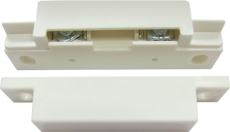
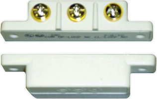
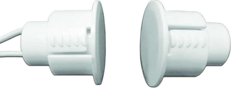
Schlage 674/679/7764/7766 Series magnetic door position switches detect open/closed door status and relay this information to a control panel, offered in surface and concealed mounting configurations for wood, hollow metal, and aluminum doors, overhead doors, and gates.

Product specifications
674-OH overhead door, floor mount
Concealed mount (679) wood door/frame (679-05), hollow metal (679-05 HM), wood door with metal frame (679-05 WD)
Current rating (679) 0.3 Amps @ 30 VDC
7764 concealed/flush mount; aluminum, wood, hollow metal door or frame; 0.25 Amps @ 30 VDC
7766 surface mount; aluminum, wood, hollow metal door or frame; 0.25 Amps @ 30 VDC
Low-voltage wiring Connection count needs review
PreparationSelect the exact member of the door-position-switch family before preparing the door and frame. For 7764 use the concealed/flush mortise preparation and the specified door/frame reinforcement. For 7766 prepare the frame for a surface-mounted switch, provide the documented wiring access and install its matching door magnet with the orientation arrows correctly aligned. Check the exact recommended magnet gap and installation drawing. The overhead 674-OH and the 679 wood/hollow-metal versions have different mounting arrangements; use their individual drawing rather than a 7764 or 7766 template.
ElectricalThe 7764 and 7766 manuals identify these as signal switches and warn against direct load switching. Their load-control examples use an interposing relay with suppression selected for the actual DC or AC coil application; do not apply a lock load directly to the signal contacts. The switched contact function and lead colours must come from the exact selected model drawing. A contact current rating does not establish a required supply voltage, and factory leads do not establish the number of field cable jackets or conductors used. Select the exact member, monitored circuit and any relay interface before specifying wiring.

Official manufacturer documents