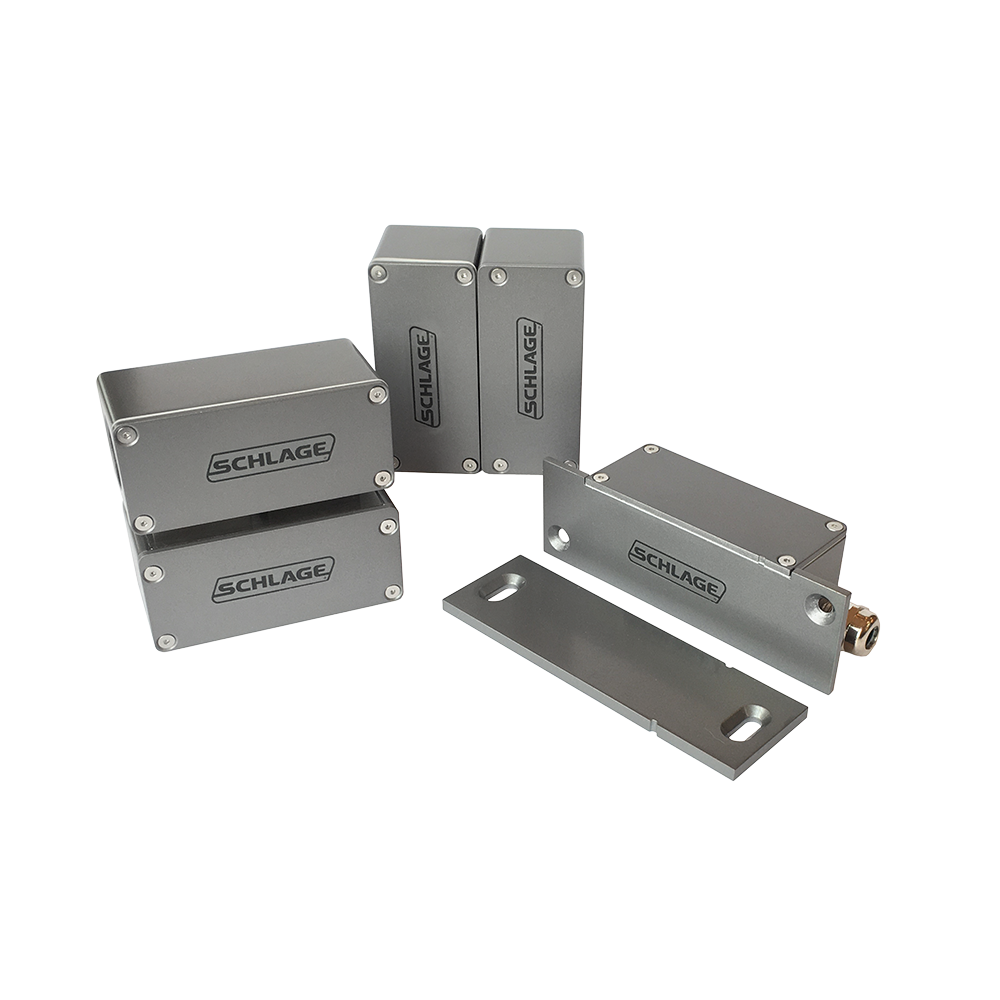
Schlage FSS1 Series Door Sensors

$50.00

The FSS1 Series Door Position Sensor (DPS) was designed as a true high security solution. Ideal for government, military & IT applications.

SKU: SCH-FSS1-SERIES-DOOR-SENSORS
Category:
Brands:

Description

The FSS1 Series Door Position Sensor (DPS) was designed as a true high security solution. Ideal for government, military & IT applications.

Brand: Schlage

Manufacturer Part Number: SCH-FSS1-SERIES-DOOR-SENSORS

Source: Official product page
Reviews

There are no reviews yet.

Be the first to review “Schlage FSS1 Series Door Sensors”

Your email address will not be published. Required fields are marked *

The PB405 PowerBolt is a mortise, right-angle electromechanical deadbolt with a 0.61" diameter bolt and 0.67" throw, available in fail-safe (PB405) or fail-secure (PB405S) versions. It installs in the door frame, includes a built-in door position switch and field-configurable relock delay, and is used for electronic access control of doors, cabinets, and drawers.

Product specifications
Models PB405 (fail-safe), PB405S (fail-secure)
Voltage 12 or 24 VDC, field selectable
Current @ 12 VDC 925 mA starting; 334 mA holding
Current @ 24 VDC 472 mA starting; 193 mA holding
Door position switch SPDT, 0.5A @ 30 VDC
Bolt diameter 0.61 in
Bolt throw 0.67 in
Dimensions 7-7/8"L x 1-1/4"W x 1-5/8"D
Relock timer delay field-selectable: 0, 3, 6, or 9 seconds
Finish satin aluminum (strike plate and mortise face)
Features door position switch; built-in re-locking option; MOV surge protection (PB405S)
Low-voltage wiring Connection count needs review
PreparationSelect the exact FSS1-F flush, FSS1-S conduit surface, or FSS1-S-NC rear-entry surface model for a hinged door. The flush sensor is mortised into the frame using its mounting tabs, with the magnet array plate in the top of the door; align their orientation marks and vertical centre lines. Surface models place the aligned sensor and magnet housings on the frame and door. Prepare and seal the appropriate cable entry and use the specified gasket and sealant where required. Follow the exact model gap and spacer instructions. Calibrate at first power-up by slowly closing and pressing the door as instructed, then test alarm and tamper operation. Recalibrate after a magnet-array replacement or significant door movement.
ElectricalThe FSS1 requires a 10-30 volts DC supply with correct polarity. Its manual lists approximately 10 mA secure operating current at 12 VDC and 45 mA during initial calibration or buzzer operation. Keep POWER, ALARM 1 and TAMPER circuits distinct. Alarm COM/NO closes when the door is secure and the sensor is powered, and opens for alarm or power failure. Tamper contacts open when tampered. The second independent alarm output is supplied on flying leads and is optional for an access-control interface. Contact ratings are separate from supply requirements. Select the actual circuits and cable route; the terminal arrangement and factory flying leads do not establish cable-jacket quantities.
Preparation requiredYes
Electrical wiring requiredYes
Conditional connectionsDC power input to the sensor: cable runs quantity unspecified; conductor count unspecified; wire type not documented; size unspecified; shielding unspecified; rating Minimum 22 AWG or 26 AWG solid (UL cable specification); endpoints DC power source to FSS1 POWER + / – terminals; when Installation configuration is Base product, all models. 10-30 VDC with polarity observed. Cable-run and conductor counts are not documented.; Alarm 1 contact output (COM and N.O.) to monitoring or alarm panel: cable runs quantity unspecified; conductor count unspecified; wire type not documented; size unspecified; shielding unspecified; rating Contact rating 0.25 A @ 30 V; endpoints FSS1 ALARM terminals (COM, N.O.) to alarm/monitoring system; when Installation configuration is Base product; control/signal circuit separate from power. The N.O. contact closes when the door is secure and power is applied. Counts are not documented.; Tamper contact output (N.C. and common): cable runs quantity unspecified; conductor count unspecified; wire type not documented; size unspecified; shielding unspecified; rating Contact rating 0.2 A @ 30 V; endpoints FSS1 TAMPER terminals to alarm/monitoring system; when Installation configuration is Base product; separate from the alarm and power circuits. Open in tamper state, closed when not tampered. Counts are not documented.; Alarm 2 contact on factory flying leads, for an access control device: cable runs quantity unspecified; conductor count unspecified; wire type not documented; size unspecified; shielding unspecified; rating unspecified; endpoints FSS1 ALARM 2 flying leads to access control device; when Installation configuration is Internal accessory connection; not field cable: Optional accessory selected: IF the second independent alarm output is used. Factory flying leads; not a field cable core and not a counted cable pull. Connecting them is optional.

Official manufacturer documents