
Description
Series: CM-RQE70A / RQE70ABK
Type: PIR ‘Request to Exit' Detectors
PIR ‘REQUEST TO EXIT' Detector
Brand: Camden
Manufacturer Part Number: CM-RQE70A
Source: Camden Controls product page
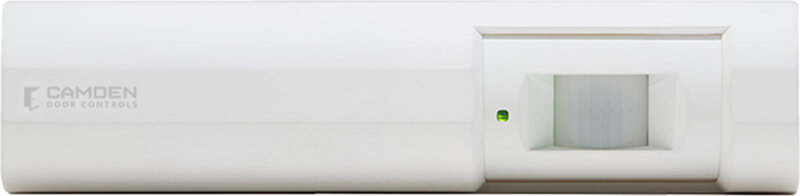
PIR ‘REQUEST TO EXIT\’ Detector
Series: CM-RQE70A / RQE70ABK
Type: PIR ‘Request to Exit' Detectors
PIR ‘REQUEST TO EXIT' Detector
Brand: Camden
Manufacturer Part Number: CM-RQE70A
Source: Camden Controls product page
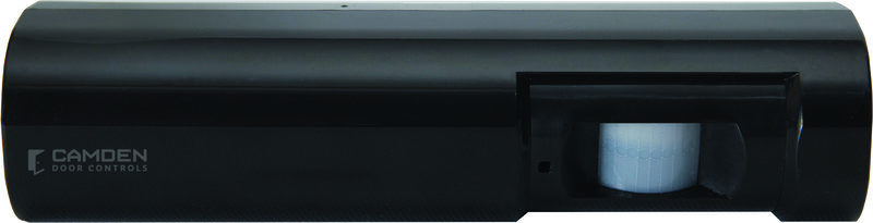
The Camden CM-RQE70 Request-to-Exit detector is a passive infrared (PIR) sensor designed for indoor use. It is UL listed as an access control device under UL 294 and is Class 1 listed for UL Canada under ULC-S319 when connected to a UL-approved access control system.
| Low-voltage wiring | Required |
|---|---|
| Basis | Structured, independently qualified product connection evidence |
| Preparation | For the interior-use RQE detector, gently remove the cover with a small flat screwdriver, loosen the vertical adjustment screw and rotate the sensor PCB assembly out of the backplate. At the selected installation height, use the manual mounting pattern and supplied wall plugs/screws appropriate to the substrate; fasten the backplate and rotate the PCB assembly back in. Adjust horizontal coverage with the two lens-louver screws and apply the tamper label, then set vertical aim and tighten the lock-down screw. Refit the cover and set screw. Select coverage, operating mode and sensitivity for the actual doorway, then complete the startup self-test and functional checks. |
| Electrical | Supply 12/24 VDC, 50 mA maximum, to J2 pin 1 power positive and J4 pin 7 power negative. Use the power source and standby provision specified in the manufacturer installation instructions. J4 relay 1a has NC1 pin 4, NO1 pin 5 and C1 pin 6; relay 1b has NC2 pin 1, NO2 pin 2 and C2 pin 3. Choose one contact pair per selected circuit and program fail mode for the actual controlled device. Relay contact rating is 3 A at 30 VDC. J2 pins 2, 3 and 4 are programmable inputs 1, 2 and 3; J2 pin 5 is their ground. Each selected external dry-contact input circuit has two conductors, but shared returns may change cable grouping. J2 pins 6/7 provide the separate tamper contact, closed with the cover installed, rated 50 mA at 12 VDC. Confirm actual terminal markings: manual prose calls this a harness while its drawing and current listing show terminals. The shown maglock circuit uses its specified protection and mode; do not treat a generic relay pair as a complete lock-power circuit. Cable gauge/type, routing and run quantities require the site design. |
| Preparation required | Yes |
| Electrical wiring required | Yes |
| Conditional connections | CM-RQE70A DC power input: cable runs quantity unspecified; 2 conductor(s); wire type not documented; size unspecified; shielding unspecified; rating Field cable type/gauge, shared-return grouping, routing and physical runs unspecified.; endpoints External DC supply to J2 pin1 positive and J4 pin7 negative; when Installation configuration is Base DC supply.; CM-RQE70A relay 1a contact loop: cable runs quantity unspecified; 2 conductor(s); wire type not documented; size unspecified; shielding unspecified; rating Field cable type/gauge, shared-return grouping, routing and physical runs unspecified.; endpoints J4 C1 pin6 and selected NO1 pin5 or NC1 pin4 to External low-voltage controlled circuit; when Installation configuration is Only if relay1a is selected; choose NO or NC for the programmed mode.; CM-RQE70A relay 1b contact loop: cable runs quantity unspecified; 2 conductor(s); wire type not documented; size unspecified; shielding unspecified; rating Field cable type/gauge, shared-return grouping, routing and physical runs unspecified.; endpoints J4 C2 pin3 and selected NO2 pin2 or NC2 pin1 to External low-voltage controlled circuit; when Installation configuration is Only if relay1b is selected; choose NO or NC for the programmed mode.; CM-RQE70A optional input 1 loop: cable runs quantity unspecified; 2 conductor(s); wire type not documented; size unspecified; shielding unspecified; rating Field cable type/gauge, shared-return grouping, routing and physical runs unspecified.; endpoints J2 pin2 input1 and pin5 ground to External selected dry-contact device; when Installation configuration is Only if input1 is used; programmed function determines device. Shared returns do not establish separate cable runs.; CM-RQE70A optional input 2 loop: cable runs quantity unspecified; 2 conductor(s); wire type not documented; size unspecified; shielding unspecified; rating Field cable type/gauge, shared-return grouping, routing and physical runs unspecified.; endpoints J2 pin3 input2 and pin5 ground to External selected dry-contact device; when Installation configuration is Only if input2 is used; programmed function determines device. Shared returns do not establish separate cable runs.; CM-RQE70A optional input 3 loop: cable runs quantity unspecified; 2 conductor(s); wire type not documented; size unspecified; shielding unspecified; rating Field cable type/gauge, shared-return grouping, routing and physical runs unspecified.; endpoints J2 pin4 input3 and pin5 ground to External selected dry-contact device; when Installation configuration is Only if input3 is used; programmed function determines device. Shared returns do not establish separate cable runs.; CM-RQE70A optional tamper loop: cable runs quantity unspecified; 2 conductor(s); wire type not documented; size unspecified; shielding unspecified; rating Field cable type/gauge, shared-return grouping, routing and physical runs unspecified.; endpoints J2 pins6 and7 to External alarm/access-control monitor; when Installation configuration is Only if cover tamper monitoring is connected. |

Reviews
There are no reviews yet.