
Description
Series: CM-1000 Series
Type: Cast Aluminum with Surface Box
Surface Mount Key Switch, SPDT N/O & N/C Maintained
Brand: Camden
Manufacturer Part Number: CM-1030
Source: Camden Controls product page
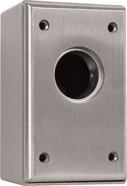
Surface Mount Key Switch, SPDT N/O & N/C Maintained
Series: CM-1000 Series
Type: Cast Aluminum with Surface Box
Surface Mount Key Switch, SPDT N/O & N/C Maintained
Brand: Camden
Manufacturer Part Number: CM-1030
Source: Camden Controls product page
Camden Door Controls, CM-1000 Series surface mount switches meet the stringent demands of key switch controls. They are designed for use with standard 1", 1 1/8", or 1 1/4" mortise cylinders, fabricated from 1/4" thick aluminum into a one-piece die-cast construction. All controls provide for one (1) or two (2) switch configurations.
| Low-voltage wiring | Required |
|---|---|
| Basis | Structured, independently qualified product connection evidence |
| Preparation | The unit is a surface-mount key switch supplied with a surface box, faceplate, gasket and lock ring. The mortise cylinder is not included and must be sourced separately. It accepts standard 1" to 1-1/4" mortise cylinders. The box has a 1/2" threaded conduit entry. The documented dimensions are 4-1/2" x 2-3/4" x 2". Mounting surface, mounting method and conduit routing are site-dependent and not specified. |
| Electrical | Base configuration: Surface Mount Key Switch, SPDT N/O & N/C Maintained. For each used changeover pole, common plus NO or common plus NC requires two external conductors; common plus both NO and NC requires three. Do not join independent commons by assumption. These are low-voltage circuit conductor counts, not physical cable-run counts. The supplied 18 AWG soldered leads do not specify field cable gauge. Common is grey; momentary NO is blue and NC orange. The maintained-contact chart lists both throw leads orange, so identify the actual terminal function before connecting. Cable type, gauge, shielding and physical run quantities depend on the selected controller/device and site routing. Optional LED circuits remain separate and require their selected DC option instructions. The standard-contact parts table and family specification give different contact ratings; verify the fitted switch rating. Contact ratings are not supply requirements. |
| Preparation required | Yes |
| Electrical wiring required | Yes |
| Conditional connections | Optional LED indicator power: cable runs quantity unspecified; conductor count unspecified; wire type not documented; size unspecified; shielding unspecified; rating unspecified; endpoints optional LED indicator to 12V or 24V supply; when Installation configuration is Optional accessory selected: IF an optional LED indicator variant is selected (-7xxx suffix, 12V or 24V). Not part of the base CM-1030. The wiring is not documented in the supplied text.; Optional LED indicator circuit (IF an LED option is selected, e.g. -7124 green 24V LED on CM-1030). The LED is wired as a DC-only circuit with its own 12 VDC or 24 VDC supply, separate from the switch contacts.: cable runs quantity unspecified; conductor count unspecified; wire type not documented; size unspecified; shielding unspecified; rating unspecified; endpoints LED red (+) lead to LED black (-) lead to external 12 VDC or 24 VDC supply; when Installation configuration is Optional accessory selected: IF an optional LED indicator is selected. The diagram shows a red (+) and black (-) LED circuit. The 12 VDC version has an integrated 560 ohm resistor and the 24 VDC version shows a 1.5 k ohm resistor. Single-colour LED options only; bi-colour LEDs use a separate 3-wire arrangement. This is not part of the base switch.; Selected base switch 1: common and NO: cable runs quantity unspecified; 2 conductor(s); wire type not documented; size unspecified; shielding unspecified; rating Field cable type, gauge, shielding and physical run quantity unspecified. Supplied18AWG solderedleads do not establish field cable gauge.; endpoints Selected low-voltage controlled equipment to CM-1030 switch 1 common and NO; when Installation configuration is For switch 1, select common and NO. This is an alternative pole configuration; do not add it to the other alternatives for the same pole. Use only the supplied switches/poles needed by the controlled equipment. No physical run count is inferred.; Selected base switch 1: common and NC: cable runs quantity unspecified; 2 conductor(s); wire type not documented; size unspecified; shielding unspecified; rating Field cable type, gauge, shielding and physical run quantity unspecified. Supplied18AWG solderedleads do not establish field cable gauge.; endpoints Selected low-voltage controlled equipment to CM-1030 switch 1 common and NC; when Installation configuration is For switch 1, select common and NC. This is an alternative pole configuration; do not add it to the other alternatives for the same pole. Use only the supplied switches/poles needed by the controlled equipment. No physical run count is inferred.; Selected base switch 1: common, NO and NC: cable runs quantity unspecified; 3 conductor(s); wire type not documented; size unspecified; shielding unspecified; rating Field cable type, gauge, shielding and physical run quantity unspecified. Supplied18AWG solderedleads do not establish field cable gauge.; endpoints Selected low-voltage controlled equipment to CM-1030 switch 1 common, NO and NC; when Installation configuration is For switch 1, select common, NO and NC. This is an alternative pole configuration; do not add it to the other alternatives for the same pole. Use only the supplied switches/poles needed by the controlled equipment. No physical run count is inferred. |


Reviews
There are no reviews yet.