Schlage 8200 Remote Desk Console

$189.99

Schlage 8200 Series remote monitor and control consoles allow both control and monitoring designed to meet a wide range of security requirements.

SKU: SCH-8200-REMOTE-DESK-CONSOLE
Category:
Brands:

Description

Schlage 8200 Series remote monitor and control consoles allow both control and monitoring designed to meet a wide range of security requirements.

Brand: Schlage

Manufacturer Part Number: SCH-8200-REMOTE-DESK-CONSOLE

Source: Official product page

Reviews

There are no reviews yet.

Be the first to review “Schlage 8200 Remote Desk Console”

Your email address will not be published. Required fields are marked *

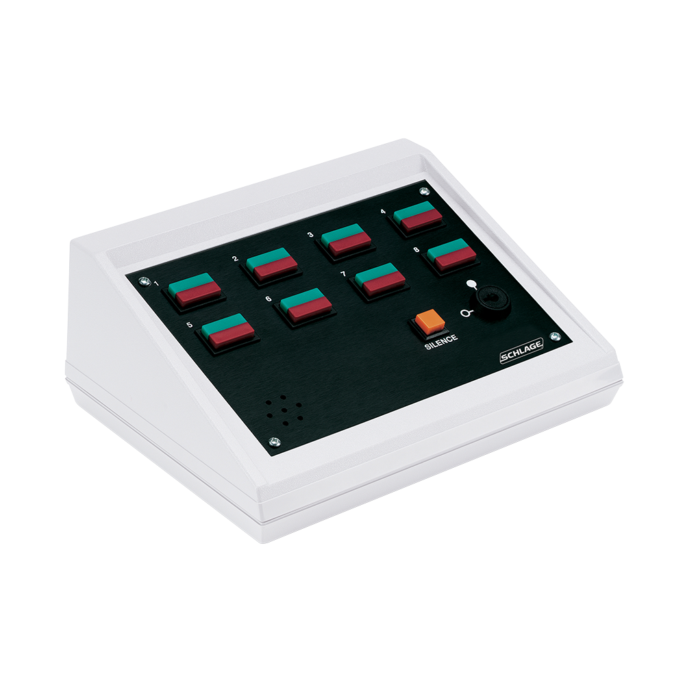
The Schlage 8200 Series remote monitor and control desk console provides control and status monitoring of electrified door hardware and accessories for up to 8 zones, with red and green lighted pushbuttons, a security keyswitch, and a signaling horn with alarm reset.

Product specifications
Models 8204 (4-zone), 8208 (8-zone)
Switch current draw 1 Amp @ 24 VDC
Lamp current draw 0.04 Amp @ 24 VDC
Alarm current draw 0.5 Amp @ 24 VDC (breaker protected)
Operating temperature 32 to 120 F (0 to 49 C)
Button types red and green pushbuttons with indicator lamps
Switch options momentary (M) or alternate action/maintained (A) per zone
Features security keyswitch, signaling horn, alarm reset
Replacement parts 8200MS (momentary), 8200AS (alternate action) pushbutton assemblies
Low-voltage wiring Connection count needs review
PreparationInstallation requires removing the I/O panel and drilling a hole in it for the wiring used, with a strain relief or cable connector if required. A 24 VDC power source must be available (UL294 listed Class 2 for UL applications). Pushbutton function (momentary or maintained) is selected per zone at order; the 4-zone or 8-zone configuration is chosen at order.
ElectricalThe 8200 console requires 24 VDC; for UL applications the instructions require a UL294-listed Class 2 power-limited supply. The internal console current excludes the indicator lamps, so size the supply for the selected lamps and connected application. Keep console power, each selected zone/lock circuit, door-position monitoring and the common alarm output distinct. The keyswitch changes pushbutton control and fail-safe/fail-secure output behaviour; user-selectable diode changes affect individual zones and require the matching instructions. Terminal maximum wire capacity and a recommended conductor range do not determine the cable required for the connected load or physical run count. Choose zone population, momentary/maintained functions, lock type and power/control mode before assigning field circuits and routes.
Preparation requiredYes
Electrical wiring requiredYes
Conditional connections24 VDC power input to console: cable runs quantity unspecified; conductor count unspecified; wire type not documented; size unspecified; shielding unspecified; rating Terminal blocks accept max 14 AWG, 18-22 AWG recommended; endpoints 24 VDC power supply to Console TB9 power terminals; when Installation configuration is Base console power; cable run count and conductor count are not stated in the supplied evidence. The diagrams show TB9 with terminals marked +, – and a ground/0 terminal, but the conductor count is not established.; Zone control/monitor wiring to controlled device (e.g., magnetic lock, electric strike, Chexit, L1910, EL device): cable runs quantity unspecified; conductor count unspecified; wire type not documented; size unspecified; shielding unspecified; rating Max 14 AWG, 18-22 AWG recommended; endpoints Console zone terminal block TB1-TB8 (GRN, RED, C, NO, NC) to Controlled or monitored door device; when Installation configuration is Applies per zone used; the connected device varies with the application and the typical wiring examples differ by device. Counts depend on the selected device and are not established.; External alarm output to horn, light or sounder: cable runs quantity unspecified; conductor count unspecified; wire type not documented; size unspecified; shielding unspecified; rating unspecified; endpoints Console alarm output to External horn/light/sounder; when Installation configuration is Optional accessory selected: IF an external horn, light or sounder is selected; the maximum load is 1/2 A @ 24 VDC. This is an optional external device circuit, not required for base operation (the console has its own internal signaling horn).

Official manufacturer documents