
Description
Get consistent output to your access control system with the highly configurable PS902 2-amp power supply.
Brand: Schlage
Category: Power Supplies
Manufacturer Part Number: PS902
Source: Official product page
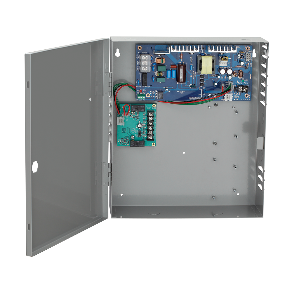
Get consistent output to your access control system with the highly configurable PS902 2-amp power supply.
Get consistent output to your access control system with the highly configurable PS902 2-amp power supply.
Brand: Schlage
Category: Power Supplies
Manufacturer Part Number: PS902
Source: Official product page
The Schlage PS902 is a 2-amp, UL 294 Class 2 filtered and regulated power supply that delivers clean, field-selectable 12 or 24 VDC output to protect downstream access control devices. It accepts universal 120/240 VAC input, supports separate battery management, and accepts one field-installable option board (e.g., relay, fire alarm interface, or fused/PTC output boards).
| Model | PS902: 2 amp Class 2 filtered and regulated power-limited output |
|---|---|
| Input voltage | 120/240 VAC, 50/60 Hz, universal input |
| Output voltage | 12 or 24 VDC, field selectable with jumper |
| Output current | 2 amps |
| Regulation | 5% regulation, 240 Vpp max ripple |
| Output protection | current-limited foldback circuit |
| Cabinet dimensions | 14"H x 12"W x 4"D |
| Cabinet finish | grey, baked enamel |
| Cabinet grade | NEMA Grade 1 |
| Weight | 9 lbs (add 4 lbs per battery) |
| Operating temperature | 32 to 120 F (0 to 49 C) |
| AC primary fuse | T3.15A, 250VAC, 5x20mm |
| Battery fuse | 7.5A 32V ATO blade style |
| Certifications | UL 294, ULC-S318, RoHS, FCC Part 15, Class 2 |
| Option board connectors | 1 |
| Supported option boards | 900-BB, 900-BBK (battery backup), 900-FA (fire alarm interface), 900-2RS (2 relay), 900-4R (4 relay), 900-4RL (4 relay w/ logic), 900-8F (8 fused outputs), 900-8P (8 PTC protected outputs), 900-KL (key lock cover) |
| Low-voltage wiring | Connection count needs review |
| Preparation | The enclosure must be firmly mounted to a solid surface indoors, using hardware suited to that surface. Mounting is with 4 screws, marking 2 top holes first. The enclosure is 14" H x 12" W x 4" D with 8 knockouts for 1/2" or 3/4" conduit. AC supply wiring is required and the AC breaker must be off during installation. |
| Electrical | The base PS902 output is rated 2 Amp DC at 12/24 VDC, selected by its output-voltage jumper. Keep the AC mains input, DC load wiring and dry status contacts distinct. Maintain the manual's minimum separation between AC and DC wiring, and between power-limited and non-power-limited wiring. The AC monitor provides dry status contacts; its contact rating is separate from supply output capacity. Battery backup, fire-alarm and distribution/relay boards are optional and must follow their own installation instructions. Select connected loads, voltage setting, optional boards and monitoring contacts before specifying field cable gauge, route or physical jacket/run quantities. Terminal positions and maximum terminal wire capacity do not establish those quantities. Manufacturer photographs may illustrate optional boards or batteries; select the required accessories separately. |
| Preparation required | Yes |
| Electrical wiring required | Yes |
| Conditional connections | AC mains input to the power supply (ground, neutral, line): cable runs quantity unspecified; conductor count unspecified; wire type not documented; size unspecified; shielding unspecified; rating unspecified; endpoints AC supply (120/240 VAC) to PS902 AC input terminal block; when Installation configuration is Base product. A ground, a neutral and a line conductor are shown for the AC input connection. The number of cable runs is not documented. 10 AWG max terminal capacity.; 12/24 VDC power output to the connected electrified device: cable runs quantity unspecified; conductor count unspecified; wire type not documented; size unspecified; shielding unspecified; rating unspecified; endpoints PS902 12/24 VDC output terminals (+/-) to Connected electrified device (load); when Installation configuration is Base product. The DC output terminal block is 2-position with 12 AWG max capacity. The load and number of cable runs are site-dependent and not documented.; AC monitor isolated SPDT (Form C dry contact) status output: cable runs quantity unspecified; conductor count unspecified; wire type not documented; size unspecified; shielding unspecified; rating unspecified; endpoints PS902 AC monitor NC/C/NO terminals to External monitoring device; when Installation configuration is Only IF the AC status monitoring contacts are used. Use and connected equipment are not documented, so counts are unknown.; Battery connection from the 900-BB battery backup board to the batteries: cable runs quantity unspecified; conductor count unspecified; wire type not documented; size unspecified; shielding unspecified; rating unspecified; endpoints 900-BB battery backup board to Batteries 1 and 2 inside enclosure; when Installation configuration is Internal accessory connection; not field cable: Optional accessory selected: IF the optional 900-BB battery backup board is selected. Red (+) and black (-) wires attach from the battery board to the batteries in the enclosure.; Battery supervision Form C dry contacts from 900-BB: cable runs quantity unspecified; conductor count unspecified; wire type not documented; size unspecified; shielding unspecified; rating unspecified; endpoints 900-BB battery supervision NO/C/NC terminals to External monitoring device; when Installation configuration is Optional accessory selected: IF the optional 900-BB battery backup board is selected and the supervision contacts are used.; Fire alarm input to the 900-FA board: cable runs quantity unspecified; conductor count unspecified; wire type not documented; size unspecified; shielding unspecified; rating unspecified; endpoints Fire alarm contact to 900-FA FA1/FA2 terminals; when Installation configuration is Optional accessory selected: IF the optional 900-FA fire alarm board is selected. Jumper J13 must be removed when the 900-FA is installed. Refer to the 900-FA instructions for details. |

Reviews
There are no reviews yet.