
Description
Series: CX-WEC Series
Type: Emergency Call For Universal Restrooms
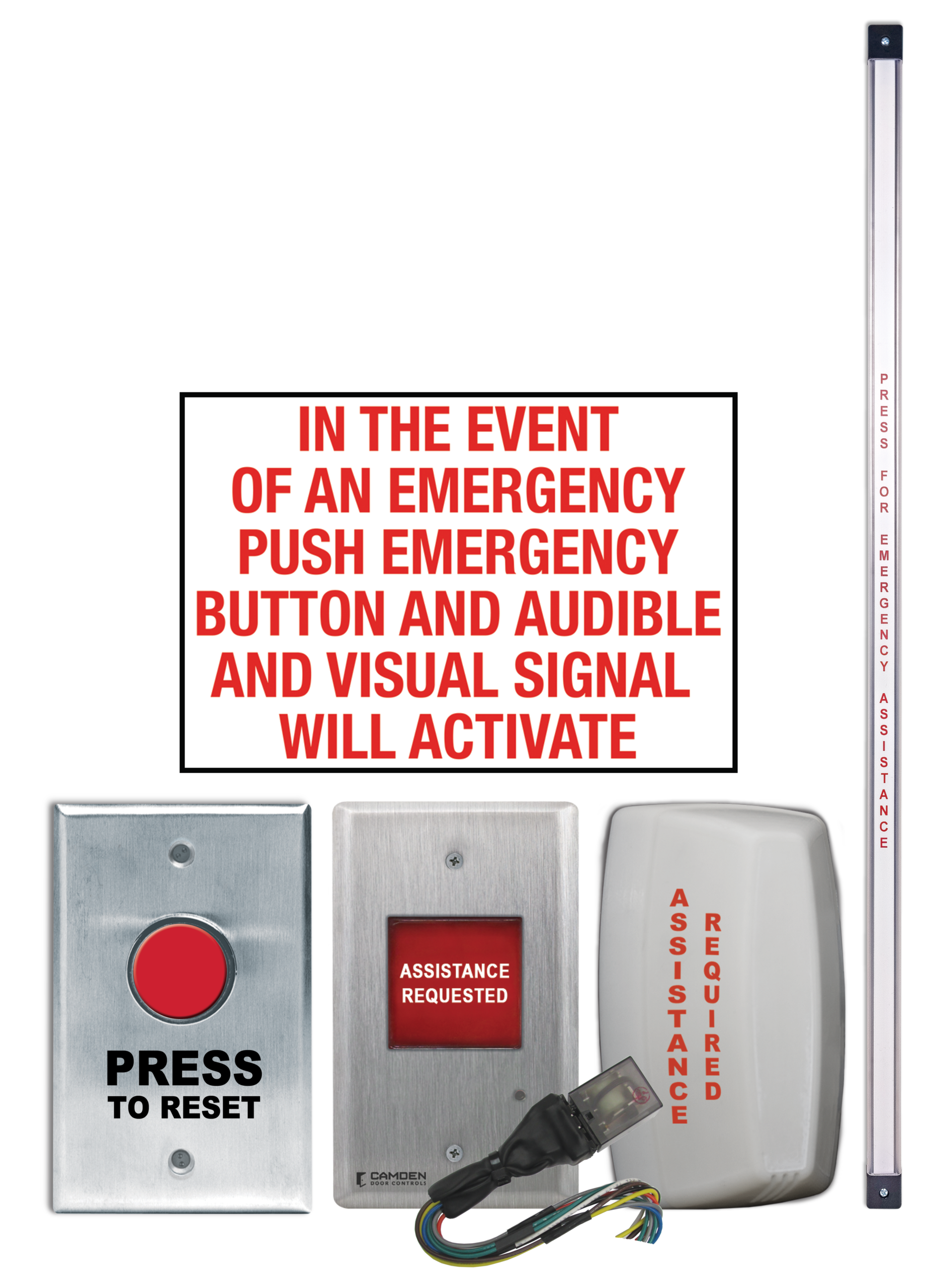
Emergency Call System Kit with Ribbon Switch and Push Button Reset
Brand: Camden
Manufacturer Part Number: CX-WEC12-TS
Source: Camden Controls product page
Emergency Call System Kit with Ribbon Switch and Push Button Reset
Series: CX-WEC Series
Type: Emergency Call For Universal Restrooms
Emergency Call System Kit with Ribbon Switch and Push Button Reset
Brand: Camden
Manufacturer Part Number: CX-WEC12-TS
Source: Camden Controls product page
Camden CX-WEC Series equipment kits are Emergency Call System packages for universal and barrier-free restrooms, meeting current OBC building code requirements. Kits include a 'PRESS FOR EMERGENCY ASSISTANCE' push button, audible and visual annunciators inside and outside the restroom, and instructional signage, with white-only or multi-color (red/green/blue/white) LED dome lights with adjustable sounder available.
| Warranty | 3 year warranty |
|---|---|
| Faceplate | single gang stainless steel (CM-450R/12 push button) |
| Sign | CM-SE21 white panel sign, 12.5" x 8.5" (317.5mm x 216mm) |
| Languages | English, French and Bilingual (suffix 'F' for French, 'FE' for French/English, 'SP' for Spanish) |
| Component power (CM-AF142SO) | 12/24 VAC/VDC |
| Compliance | City of Toronto compliant package (CX-WEC12-TS & CX-WEC13-TS) includes 33-1/2" vertical ribbon switch |
| Low-voltage wiring | Required |
| Basis | Structured, independently qualified product connection evidence |
| Preparation | Locate the tape switch, mark the two mounting holes and wiring hole, drill using the manual's specified sizes, insert the wiring and secure the switch with the supplied fasteners. Mount the CM-AF501SO inside annunciator and CM-AF141SO corridor dome light on their single-gang electrical boxes. Fit the dome-light gasket and O-ring with the specified bottom opening, lock the lens, apply labels and adjust sound volume. Mount the CM-8010R/13 normally-closed momentary push-button reset on its single-gang box. |
| Electrical | The kit uses a CX-LRS24 latching relay with a momentary tape-switch activation input and CM-8010R/13 normally-closed momentary push-button reset. The annunciator and dome light provide inside and corridor audible/visual notification. The system diagram specifies 24 VDC and the component table rates the CX-LRS24 at 24 V AC/DC, while the relay lead sketch labels 12/24 V AC/DC; confirm the delivered relay before selecting a different supply. DC is required when integrated with a Camden restroom control kit. Optional remote-monitoring Form C and WC-interface NC outputs are separate from the base activation and reset inputs. Check both AC and DC source voltage before energizing. Switch contact ratings and factory lead sizes do not specify the field power supply, cable gauge or number of cable jackets/runs. Choose the field wiring from the actual layout and selected optional interfaces. |
| Preparation required | Yes |
| Electrical wiring required | Yes |
| Conditional connections | 24 VDC power to the CX-LRS24 relay (white and black leads), the CM-AF501SO annunciator and the CM-AF141SO dome light (+V / -V): cable runs quantity unspecified; conductor count unspecified; wire type not documented; size unspecified; shielding unspecified; rating unspecified; endpoints 24 VDC power supply to CX-LRS24 to CM-AF501SO to CM-AF141SO; when Installation configuration is Base kit as wired in Figure 6.2 with a 24 VDC supply. The supply itself is external to the kit.; CX-LRS24 blue lead to the CM-AF501SO annunciator and gray lead to the CM-AF141SO dome light (relay-switched outputs): cable runs quantity unspecified; conductor count unspecified; wire type not documented; size unspecified; shielding unspecified; rating unspecified; endpoints CX-LRS24 to CM-AF501SO to CM-AF141SO; when Installation configuration is Base kit as wired in Figure 6.2. Cable run structure is not documented.; CX-LRS24 NC dry output (gray and orange leads) interface to a WC system: cable runs quantity unspecified; conductor count unspecified; wire type not documented; size unspecified; shielding unspecified; rating unspecified; endpoints CX-LRS24 to WC (restroom) system; when Installation configuration is Optional accessory selected: IF a connection to a WC / restroom control system is wanted. Diagram label: NC – Interface to WC System.; CX-LRS24 Form C output (blue NO, gray COM, orange NC) for remote monitoring: cable runs quantity unspecified; conductor count unspecified; wire type not documented; size unspecified; shielding unspecified; rating unspecified; endpoints CX-LRS24 to remote monitoring equipment; when Installation configuration is Optional accessory selected: IF remote monitoring is wanted. Using all Form C terminals is not implied.; Power supply to the CX-LRS24 relay assembly: cable runs quantity unspecified; conductor count unspecified; wire type not documented; size unspecified; shielding unspecified; rating unspecified; endpoints 24 VDC power supply +V/-V to CX-LRS24 (white and black leads); when Installation configuration is Base kit as shown in the CX-WEC12-TS wiring diagram. The supply is 24 VDC; the instructions state that VDC must be used when the kit is integrated with a Camden Restroom Control Kit.; Power for the CM-AF501SO annunciator and the CM-AF141SO corridor dome light: cable runs quantity unspecified; conductor count unspecified; wire type not documented; size unspecified; shielding unspecified; rating unspecified; endpoints 24 VDC supply to CM-AF501SO to CM-AF141SO to CX-LRS24 gray and blue switched output leads; when Installation configuration is Base kit as drawn in the wiring diagram, where the CX-LRS24 gray and blue outputs feed the annunciator and the dome light. These devices accept 12 to 24 V AC/DC (annunciator 12 to 30 V AC/DC).; Optional relay output to external equipment: Form C remote monitoring and NC interface to a WC system: cable runs quantity unspecified; conductor count unspecified; wire type not documented; size unspecified; shielding unspecified; rating unspecified; endpoints CX-LRS24 NO/COM/NC leads (blue, gray, orange) to CX-LRS24 NC pair (gray, orange) for the WC system to external monitoring equipment or WC system; when Installation configuration is Optional accessory selected: IF an external monitoring system or WC system interface is selected. The NO and NC outputs are dry contacts available for external equipment, and the manufacturer does not state that they must be wired.; CX-WEC12-TS external tape-switch activation pair: cable runs quantity unspecified; 2 conductor(s); wire type not documented; size unspecified; shielding unspecified; rating Field cable gauge/type, jacket/run quantity and routing unspecified.; endpoints Wall-mounted tape switch to CX-LRS24 activation NO/COM input; when Installation configuration is Only the exact CX-WEC12-TS circuit in Figure6.2; separate wall device connected to the relay. Field routing and physical cable grouping require installation selection.; CX-WEC12-TS external NC reset push-button pair: cable runs quantity unspecified; 2 conductor(s); wire type not documented; size unspecified; shielding unspecified; rating Field cable gauge/type, jacket/run quantity and routing unspecified.; endpoints Wall-mounted CM-8010R/13 NC reset contact to CX-LRS24 reset input brown/yellow; when Installation configuration is Only the exact CX-WEC12-TS circuit in Figure6.2; separate wall device connected to the relay. Field routing and physical cable grouping require installation selection. |

Reviews
There are no reviews yet.