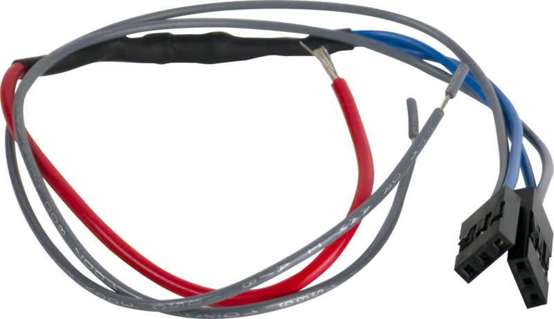
Camden CM-9600/C – Cable for remote activation/control of switch LED

$25.00

Cable for remote activation/control of switch LED

SKU: CM-9600/C
Category:
Brands:

Description

Series: CM-9600/9610

Type: Illuminated Piezoelectric Push/Exit Switch

Configuration: Remote Activation/Control

Cable for remote activation/control of switch LED

Brand: Camden

Manufacturer Part Number: CM-9600/C

Source: Camden Controls product page
Reviews

There are no reviews yet.

Be the first to review “Camden CM-9600/C – Cable for remote activation/control of switch LED”

Your email address will not be published. Required fields are marked *

(114mm) CM-9600/7 Camden Door Controls, CM-9600 and CM-9610 Series flush mount illuminated piezo push switches offer high visibility and weather/vandal resistance. The units feature a 1 ¾” heavy duty stainless steel faceplate and adjustable 40 second timer. The CM-9600 is single gang (2 3/4”) width and the CM-9610 is only (1 3/4”) wide, (45mm) perfect for door frames or narrow areas.

Product specifications
Low-voltage wiring Connection count needs review
PreparationVerify that the supplied accessory is the V2 harness shown in the manufacturer diagram. Insert its connector blocks side-by-side on the host control pins with the blank empty positions towards the bottom edge. Select the external LED-control circuit before connecting. For the documented 24VDC circuit retain the resistor; for 12VDC remove only the resistor, preserving the joined blue wires and remaining harness. No mounting cutout or field cable-run specification is given for the harness itself.
ElectricalThe V2 harness joins its two internal blue wires through a resistor to one red connection lead and provides two grey LED-control leads. In the documented external circuit, red connects to supply positive; the grey lead on the green-control side connects to the relay/switch NO contact and the grey lead on the red-control side connects to NC. Relay/switch common connects to supply negative. The drawing specifies 24VDC with the resistor retained or 12VDC with only the resistor removed. These are accessory connection instructions, not an independent host-power specification. Factory harness leads do not establish field conductor extensions, cable type, gauge, shielding or physical cable runs.
Conditional connectionsHarness gray leads for LED color control: N.O. contact turns on the green LED, N.C. contact turns on the red LED: cable runs quantity unspecified; conductor count unspecified; wire type not documented; size unspecified; shielding unspecified; rating unspecified; endpoints CM-9600 green LED control side to CM-9600 red LED control side to external switch or relay N.O. contact to external switch or relay N.C. contact; when Installation configuration is Optional accessory selected: IF the CM-9600/C remote LED control harness is selected. The product sheet says closing the appropriate open circuit changes the LED color. Cable run count is not documented.; V2 factory harness lead ends for external LED control: cable runs quantity unspecified; conductor count unspecified; wire type not documented; size unspecified; shielding unspecified; rating Factory harness: one red and two grey free leads; internal blue pair joined. Field extensions, gauge, shielding and cable runs unspecified.; endpoints CM-9600 host LED-control pins to Factory harness red and two grey free lead ends; when Installation configuration is Internal accessory connection; not field cable: V2 harness only. Factory lead count is distinct from field conductor extensions and physical cable runs; use the documented external relay/control configuration.

Official manufacturer documents