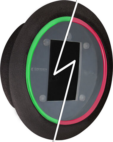
Camden CM-57GR – Flush, 4-1/2″ Round, RED/GREEN, c/w sounder, mount box

$50.00

Flush, 4-1/2\” Round, RED/GREEN, c/w sounder, mount box

SKU: CM-57GR
Category:
Brands:

Description

Series: CM-54, CM-55 & CM-57 Series

Type: Illuminated Push Plate Enclosures & Kits

Configuration: AURA™ ILLUMINATED ENCLOSURES

Flush, 4-1/2" Round, RED/GREEN, c/w sounder, mount box

Brand: Camden

Manufacturer Part Number: CM-57GR

Source: Camden Controls product page

Additional information

graphic

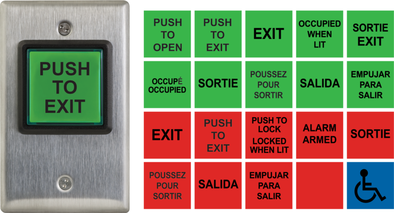
/1 blank, /2 wheelchair blue, /2AL wheelchair+arrow left, /2AR wheelchair+arrow right, /3 push to open black, /3F poussez pour ouvrir blac, /4 wheelchair+push to open, /4AL wheelchair+arrow left bl, /4AR wheelchair+arrow right b, /4F wheelchair+french black, /8 push to lock black, /8B lock symbol+push to lock, /8D push to lock door black, /8F poussez pour verrouiller

Reviews

There are no reviews yet.

Be the first to review “Camden CM-57GR – Flush, 4-1/2″ Round, RED/GREEN, c/w sounder, mount box”

Your email address will not be published. Required fields are marked *

Camden's Aura Illuminated push plate switch series provides high-visibility, ADA-compliant door activation switches available in red, green, or blue illumination, with an audible sounder and Form 'C' contacts. The line is offered in surface-mount square (CM-54i), flush-mount square (CM-55i), and flush-mount round (CM-57GR) configurations.

Product specifications
Voltage 12V or 24V AC/DC
Current draw 130mA
Contact type 1 Form 'C'
Contact rating 3 Amps @ 24V AC/DC
Dimensions CM-54i: 5 1/4" W x 5 1/4" H x 2" D (133mm x 133mm x 51mm); CM-55i: 6 1/2" W x 6 1/2" H x 2" D (165mm x 165mm x 51mm); CM-57GRB: 6 5/8" DIA. x 2" D (168mm x 51mm)
Low-voltage wiring Connection count needs review
PreparationFor the CM-57GR flush box, assemble the drywall clamp, choose the wire entry or centre knockout and cut the drywall using the actual supplied template. Pull wiring through, seat the clamp behind the drywall and tighten the 8-32 screws until the box is firmly mounted. Install optional signage first. Route wiring through the circuit-board centre opening, secure the board with its two supplied screws, then route the local push-switch wires through the diffuser. Fit any selected TX-9 before fitting the board and diffuser. Attach the push plate with its supplied Allen screws and hand-tighten; connect power and test. Confirm the delivered box/template before cutting because published dimensions differ.
ElectricalSupply 12 or 24 V AC/DC to the two power terminals; the diagram states they are not polarity sensitive. The CM-57GR manual states 150 mA maximum, while the shared specification states 130 mA. Confirm the delivered revision and supply sizing with Camden. The illustrated direct low-voltage door input uses relay COM and NO; NC is unused in that example. Optional remote LED colour change uses a remote dry-contact pair; select LOCAL and omit that pair when colour follows the push switch. CM-57GR additionally provides an optional remote-disable dry-contact pair. The push-switch connection within the box and optional TX-9 leads are local connections, not additional external cable runs. The 3 V DC output is for TX-9 only. Manual relay rating is 3 A at 30 VDC, while the shared specification says 3 A at 24 V AC/DC; confirm the applicable contact rating before choosing a load. Set speaker, relay and colour operation from the actual labelled board; choose cable type, gauge, routing and physical run quantities for the installation.
Preparation requiredYes
Conditional connectionsPower for the TX-9 RF transmitter: cable runs quantity unspecified; conductor count unspecified; wire type not documented; size unspecified; shielding unspecified; rating unspecified; endpoints CM-57GR circuit board (3V DC output) to TX-9 transmitter; when Installation configuration is Internal accessory connection; not field cable: Optional accessory selected: IF the optional TX-9 transmitter is selected: it is attached and wired before the circuit board is installed in the enclosure. This is not a field cable run, and it applies only to the accessory.; CM-57GR 12/24 V AC/DC supply: cable runs quantity unspecified; 2 conductor(s); wire type not documented; size unspecified; shielding unspecified; rating Cable type/gauge/shielding, routing and physical run quantity are installation-specific.; endpoints External low-voltage supply to Enclosure power terminals; when Installation configuration is Base enclosure power input; terminals not polarity sensitive.; CM-57GR normally-open low-voltage door input: cable runs quantity unspecified; 2 conductor(s); wire type not documented; size unspecified; shielding unspecified; rating Cable type/gauge/shielding, routing and physical run quantity are installation-specific.; endpoints Relay COM and NO to Selected external low-voltage door input; when Installation configuration is Illustrated NO/COM direct wired configuration only; NC unused.; CM-57GR optional remote LED colour contact: cable runs quantity unspecified; 2 conductor(s); wire type not documented; size unspecified; shielding unspecified; rating Cable type/gauge/shielding, routing and physical run quantity are installation-specific.; endpoints Enclosure remote colour terminals to External dry-contact switch or relay; when Installation configuration is Only if remote LED colour operation is selected; omitted for LOCAL operation.; CM-57GR optional remote-disable contact: cable runs quantity unspecified; 2 conductor(s); wire type not documented; size unspecified; shielding unspecified; rating Cable type/gauge/shielding, routing and physical run quantity are installation-specific.; endpoints Remote-disable terminals to External dry-contact disable switch; when Installation configuration is Only if optional remote disable is selected.

Official manufacturer documents